AD9850 Waveform Generator

The Circuit
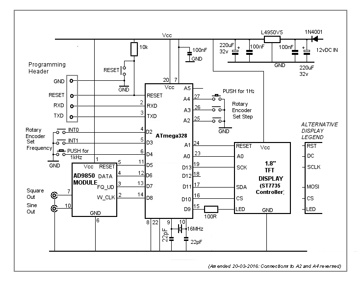
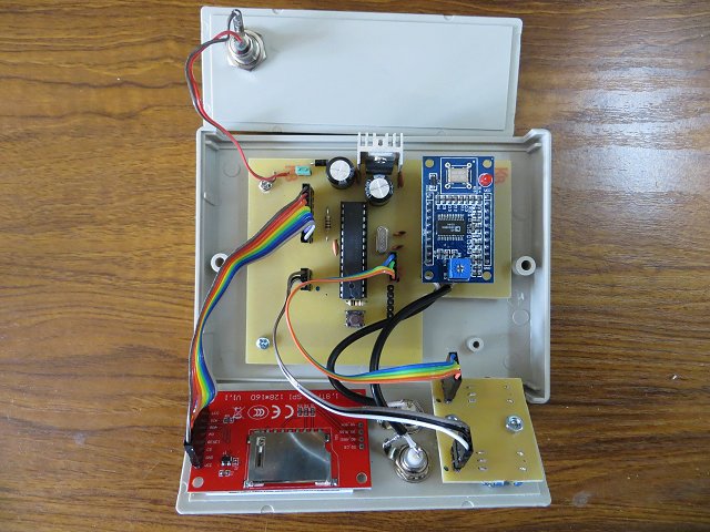
The circuit is based on the AD9850 DDS Module which is available from various sources such as eBay, Banggood, etc. Although it claims to operate up to 40 MHz, I found the output voltage started to drop off at about 2.6 MHz - both the 50 MHz digital 'scope and the 20 MHz analogue 'scope showed identical results. Therefore, I've limited the available frequency range from 10 Hz to 10 MHz in the software.
The desired frequency is set in the AD9850 module by clocking data to its DATA pin. The ATmega328 digital pins D5, D6, D7 and D8 connect to the AD9850 module's pins RESET, DATA, FQ_UD and W_CLK respectively. "In phase" sine and square wave outputs are available from the AD9850 module pins 10 and 7. The square wave's duty cycle is adjusted with a pre-set potentiometer on the module itself. I did consider removing the pot and using a panel-mounted one instead but I decided against it for this simple project. I just adjusted the pot for a 50% duty cycle (ie equal mark-space ratio) and left it at that.
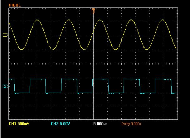
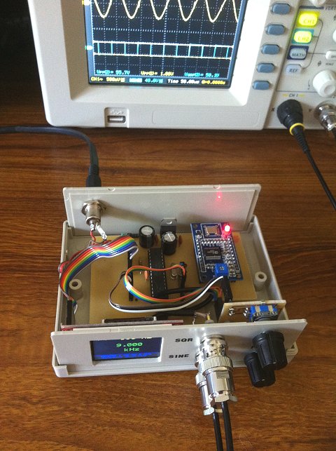
Over the 10 Hz to 2.5 MHz frequency range, the peak-to-peak sinewave output is consistent at about 1.08 volts. The square wave is around 5 volts peak-to-peak.
An interrupt-driven rotary encoder, connected to the ATmega328 interrupt pins (D2 and D3), adjusts the frequency between 10 Hz and 10 MHz in pre-set steps. Pushing the rotary encoder's button (connected to D4) resets the frequency to 1 kHz.
The steps are set with a second rotary encoder (not interrupt-driven) connected to ATmega328 pins A2 and A3. The steps are determined in software - I've set them to 1 Hz, 10 Hz, 50 Hz, 100 Hz, 500 Hz, 1 kHz, 2.5 kHz, 5 kHz, 10 kHz, 100 kHz and 500 kHz. Pushing the encoder's button - connected to A4 - resets the step to 1 Hz.
The 1.8" TFT display connects to the ATmega328 pins A1, A0, D13, D12, D11 and D10. D10 to D13 are the ATmega328's SPI pins and the software uses an Adafruit library. Pin D9 connects to the display's LED pin via a 100 ohm resistor. D9 is a PWM pin so the display's backlight brightness can be adjusted if desired. I've set it in software to '255' -ie maximum brightness.
There are some very similar 1.8" TFT displays available - the one I used has an ST7735 controller IC. Some of the other displays use a different controller (and different Adafruit library) and - not provided for in the PCB layout - require 1k series resistors in each IO lead.
I've used a 5 volts 1.5A regulator in the power supply section. With a 12v DC input, the regulator does run slightly warm so I fitted it with a small heatsink. I included a jumpered link in the PCB design so an on/off switch could easily be added.
The two rotary encoders are soldered to the small front-panel-mounted PCB with the track side up. The encoders I used had metal bases so I slipped a piece of thin insulation under them.
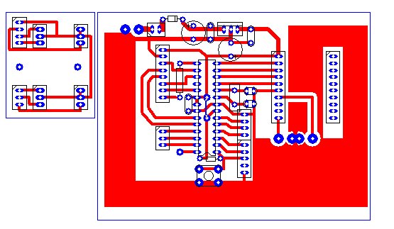
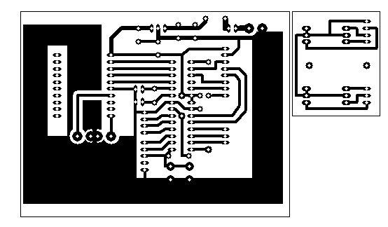
PCB Layout
Download Circuit Wizard PCB Layout.Download PCB layout in PDF Format.
Construction
Main Components
| 1.8" TFT Display Module (ST7735 Controller) | Bang-good |
| AD9850 DDS Module | Bang-good |
| 50x130x100mm enclosure | eBay (top-quality-tools) |
The ATmega328 'sketch'
AD9850 DatasheetAD9850 DDS Module
Arduino Libraries:
Adafruit_GFX Library
Adafruit_ST7735 Library
Rotary Encoder Library
/* Based on AD9851 code from Andrew Smallbone - modified for AD9850
   http://www.rocketnumbernine.com/2011/10/25/programming-the-ad9851-dds-synthesizer
 */

#include <Adafruit_GFX.h>       // Core graphics library https://github.com/adafruit/Adafruit-GFX-Library
#include <Adafruit_ST7735.h>    // Hardware-specific library https://github.com/adafruit/Adafruit-ST7735-Library
#include <SPI.h>

#include <Rotary.h>            //  Rotary encoder: https://github.com/brianlow/Rotary

int TFT_LED = 9;
#define TFT_SCLK 13             // 1.8" TFT Display.
#define TFT_MOSI 11             //
#define TFT_CS   10
#define TFT_RST  A1
#define TFT_DC   A0

Adafruit_ST7735 tft = Adafruit_ST7735(TFT_CS,  TFT_DC, TFT_RST);

#define AD9850_CLOCK 125000000         // Module crystal frequency. Tweak here for accuracy.

#define W_CLK 8                        // AD9850 Module pins.
#define FQ_UD 7
#define DATA  6
#define RESET 5

#define stepPin1 A3                    // Set 'Step' rotary encoder pins
#define stepPin2 A2
int forceHzStep = A4;                  // 'Step' rotary encoder's push button - Set 1 Hz steps.
int forcekHz = 4;                     // Interrupt-driven encoder's push button - force 1kHz freq.

Rotary i = Rotary(stepPin1, stepPin2); // Rotart encoder for setting increment.
Rotary r = Rotary(2, 3);               // Rotary encoder for frequency connects to interrupt pins

long unsigned int freq = 1000;         // Set initial frequency.
long unsigned int freqOld = freq;

long int timer;


const char* stepText[11] = {"  1 Hz", " 10 Hz", " 50 Hz", "100 Hz", "500 Hz", "  1 kHz", "2.5 kHz",
                     "  5 kHz", " 10 kHz", "100 kHz", "500 kHz"};

int stepPointer = 0;
unsigned long  incr = 0;
String units = stepText[stepPointer];

#define pulseHigh(pin) {digitalWrite(pin, HIGH); digitalWrite(pin, LOW); }


 // transfers a byte, a bit at a time, LSB first to the 9850 via serial DATA line
void tfr_byte(byte data) {
  for (int i = 0; i < 8; i++, data >>= 1) {
    digitalWrite(DATA, data & 0x01);
    pulseHigh(W_CLK);   //after each bit sent, CLK is pulsed high
  }
}

void sendFrequency(double frequency) {
  int32_t freq1 = frequency * 4294967295/AD9850_CLOCK;  // note 125 MHz clock on 9850
  for (int b = 0; b < 4; b++, freq1 >>= 8) {
    tfr_byte(freq1 & 0xFF);
  }
  tfr_byte(0x000);                     // Final control byte, all 0 for 9850 chip
  pulseHigh(FQ_UD);                    // Done!  Should see output
}


void setup() {

  pinMode(stepPin1, INPUT_PULLUP);     // Pins for step rotary encoder on analogue pins A2, A3
  pinMode(stepPin2, INPUT_PULLUP);

  pinMode(2, INPUT_PULLUP);            // Pins for interrupt-driven rotary encoder and push buttons
  pinMode(3, INPUT_PULLUP);
  pinMode(forceHzStep, INPUT_PULLUP);
  pinMode(forcekHz, INPUT_PULLUP);

  pinMode(FQ_UD, OUTPUT);              // Configure pins for output to AD9850 module.
  pinMode(W_CLK, OUTPUT);
  pinMode(DATA, OUTPUT);
  pinMode(RESET, OUTPUT);

  pinMode(TFT_RST, OUTPUT);            // Configure pins for output to TFT display.
  pinMode(TFT_DC, OUTPUT);
  pinMode(TFT_LED, OUTPUT);

  analogWrite(TFT_LED, 255);           // Adjust backlight brightness.

 // Configure interrupt and enable for rotary encoder.
  PCICR |= (1 << PCIE2);
  PCMSK2 |= (1 << PCINT18) | (1 << PCINT19);
  sei();


  tft.initR(INITR_BLACKTAB);           // initialize a ST7735S chip, black tab

  tft.setRotation(3);
   tft.setTextWrap(false);              // Allow text to run off right edge
  tft.fillScreen(ST7735_BLACK);

  tft.setCursor(15, tft.height() -20);
  tft.setTextSize(1);
  tft.drawFastHLine(0, tft.height() - 23, tft.width()-10, ST7735_BLUE);
  tft.setTextColor(ST7735_BLUE);
  tft.println("AD9850 1 Hz to 5 MHz ");
  tft.print("   sinewave generator");

  // Initialise the AD9850 module.
  pulseHigh(RESET);
  pulseHigh(W_CLK);
  pulseHigh(FQ_UD);    // this pulse enables serial mode - Datasheet page 12 figure 10

  updateDisplay();       // Update the TFT display.
}

void getStep() {
  switch(stepPointer) {
    case 0:  incr = 1; break;
    case 1:  incr = 10; break;
    case 2:  incr = 50; break;
    case 3:  incr = 100; break;
    case 4:  incr = 500; break;
    case 5:  incr = 1000; break;
    case 6:  incr = 2500; break;
    case 7:  incr = 5000; break;
    case 8:  incr = 10000; break;
    case 9:  incr = 100000; break;
    case 10: incr = 500000; break;
  }
}


void updateDisplay() {
  getStep();                          //
  units = stepText[stepPointer];

  tft.fillRect(0, 15, 160, 20, ST7735_BLACK);

  tft.setTextColor(ST7735_YELLOW);
  tft.setCursor(10, 20);
  tft.setTextSize(1);
  tft.print("Step: ");
  tft.setTextSize(2);
  tft.setCursor(60, 15);
  tft.print(units);

  tft.fillRect(0, 40, 160, 60, ST7735_BLACK);
  tft.setTextColor(ST7735_GREEN);
  tft.setTextSize(2);
  if (freq < 1000) {
    tft.setCursor(78, 50);
    if (freq < 1000) tft.print(" ");
    if (freq < 100) tft.print(" ");
    tft.print(freq);
    tft.setCursor(58, 75);
    tft.print(" Hz");
  } else
  if (freq < 1000000) {
   tft.setCursor(40, 50);
   if (freq < 10000) tft.print(" ");
   tft.print((float)freq/1000, 3);
   tft.setCursor(58, 75);
   tft.print(" kHz");
  }  else {
   format(freq);
   tft.setCursor(58, 75);
   tft.print(" MHz");
  }
}

void format(long value) {
  int M = (value/1000000);
  int T100 = ((value/100000)%10);
  int T10 = ((value/10000)%10);
  int T1 = ((value/1000)%10);
  int U100 = ((value/100)%10);
  int U10 = ((value/10)%10);
  int U1 = ((value/1)%10);
  tft.setCursor(25, 50);
  tft.print(M);tft.print(".");tft.print(T100);tft.print(T10);tft.print(T1);
  tft.print(",");tft.print(U100);tft.print(U10);tft.print(U1);
}

void loop() {
  // Check 'Step' rotary encoder.
  unsigned char result = i.process();
  if (result) {
    if (result == DIR_CW)  {if (stepPointer < 10) stepPointer++;}
    if (result == DIR_CCW) {if (stepPointer > 0) stepPointer--;}
    updateDisplay();
  }

  if (digitalRead(forceHzStep) == LOW) {
    stepPointer = 0;
    updateDisplay();
    delay(50);
  }

  if (digitalRead(forcekHz) == LOW) {
    freq = 1000;
    sendFrequency(freq);
    updateDisplay();
    delay(350);
  }
  if (freqOld != freq) {
    sendFrequency(freq);
    updateDisplay();
    freqOld = freq;
  }
}

ISR(PCINT2_vect) {
  unsigned char result = r.process();
  if (result) {
    if (result == DIR_CW) {
      if ((freq + incr) <= 10000000) freq += incr;
    } else {
      if ((freq - incr) >= 10) freq -= incr;
    }
    if (freq <= 10)  freq = 10;
    if (freq >=10000000) freq = 10000000;
  }
}