Programming the ATtiny85
The ATtiny85 is programmed using the Arduino environment with either an Arduino Uno or a dedicated programmer.It's necessary to define the ATtiny85 core so the Arduino IDE knows about its pins. Be aware there are a couple of different libraries for the ATtiny85 that treat the ATting85's internal registers differently.
The library I used in the Arduino brakelight Sketch is arduino-tiny. The 'README' included in the downloaded zip package contains full instructions for installing it into the Arduino IDE.
There are dozens of websites detailing how to use the Arduino Uno as a programmer - particularly for the ATtiny85 - so I won't repeat them in detail here.
In brief, the steps are:
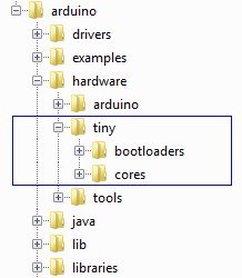
- Download the arduino-tiny library (arduino-tiny) and, with the
Arduino IDE closed, extract the files
to the main Arduino hardware folder. Something like:
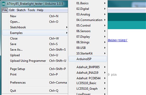
- Open the Arduino IDE and open ArduinoISP from the Examples folder. Make sure the Arduino Uno is
selected in Tools | Boards and upload the ArduinoISP sketch to the Uno in the usual way:
- Power down the Uno and connect it to the ATtiny85 as follows:
Arduino - ATtiny85 (Uno pin designations) (actual IC pin numbers) 5v - Pin 8 GND - Pin 4 D13 - Pin 7 (SCK) D12 - Pin 6 (MISO) D11 - Pin 5 (MOSI) D10 - Pin 1 (Reset) - When the Arduino Uno is acting as a programmer, it's necessary to disable its auto-reset circuit. To do this,
connect a 10uF capacitor between RESET and GND on the Arduino Uno board (Capacitor negative to GND). The capacitor 'absorbs' the auto-reset pulse from the USB/serial and prevents the Uno's ATmega328 seeing it.
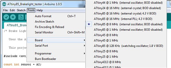
- From the Arduino Tools | Board menu, select the ATtiny85 chip: ATtiny85 @ 8 MHz (internal oscillator; BOD disabled):
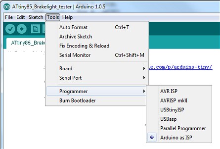
- From the Arduino Tools menu, select Programmer | Arduino as ISP.
- Power up the Arduino Uno (with the USB cable), ensure the correct COM port is still selected and, from the Tools
menu, select Burn Bootloader. This doesn't actually burn a bootloader in the ATtiny85 but it does set the internal
fuses to match the board type we selected in step 5.
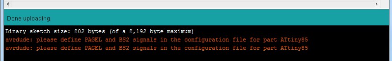
- Finally, load the brakelights Sketch into the Arduino IDE and hit Upload in the usual way. You
will see the errors shown below. They only apply if you're using an external parallel programmer so it's safe to
ignore them. The ATtiny85 should now be successfully programmed with the brakelights sketch.
If you use an external stand-alone programmer, such as the one shown here, most of the steps are the same except, as you won't be using the Arduino Uno as the programmer, the 10uF capacitor isn't used and the wiring to the ATtiny85 is already in place. Also, the programmer will already have the ArduinoISP loaded.
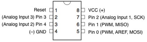
If you want to try some of the simpe Arduino examples before you program the ATtiny85 with the brakelights sketch (for example, the Blink example), remember that the pinout on the ATtiny85 is completely different from the ATmega328 used in the Uno.
/* Brake Light Tester (c) 2014 vwlowen.co.uk

   Uses the Arduino-tiny 'core' https://code.google.com/p/arduino-tiny/

   This project uses the ATtiny85  */

#include <avr/sleep.h>

const int sensor = A2;

const int testButton = 2;                      //PB2 is INT0 pin
const int redLED = 1;
const int greenLED = 0;

int activeLED = redLED;
int ambientLight;
int delta = 50;

unsigned long timeoutTimer;
unsigned long timeoutInterval = 30000;          // 30 seconds

void setup() {
  pinMode(testButton, INPUT);
  digitalWrite(testButton, HIGH);              // Enable internal pullup

  pinMode(redLED, OUTPUT);
  pinMode(greenLED, OUTPUT);
  digitalWrite(greenLED, LOW);

  GIMSK |= 1<<PCIE;                            // Enable Pin Change Interrupt
  PCMSK |= 1<<PCINT2;                          // Watch for Pin Change (Falling) on D2 (PB2)
}

void sleep() {

  ADCSRA = 0;                                  // ADC to off

  set_sleep_mode(SLEEP_MODE_PWR_DOWN);
  sleep_enable();                              // Set the Sleep Enable bit
  sleep_mode();

  sleep_disable();                             // Waking up.

  ADCSRA = 0x80;                               // ADC to on.
}                                              // ATtiny85 returns to setup() ?


ISR(PCINT2_vect) {                              // Interrupt Service Routine
}

void loop() {
  activeLED = redLED;
  timeoutTimer = millis();

  digitalWrite(activeLED, HIGH);
  digitalWrite(greenLED, LOW);

 for(int i=0; i<5; i++) {
   delay(200);
   digitalWrite(activeLED, LOW);
   delay(500);
   digitalWrite(activeLED, HIGH);
 }
  ambientLight = analogRead(sensor);
  while(timeoutTimer + timeoutInterval > millis() )  {
    digitalWrite(activeLED, HIGH);

     if (analogRead(sensor) > (ambientLight + delta)) {    // light seen. greenLED becomes active LED
        activeLED = greenLED;
        digitalWrite(redLED, LOW);
     }
  }
  digitalWrite(redLED, LOW);
  digitalWrite(greenLED, LOW);
  sleep();
}