Car Battery Charger Alert
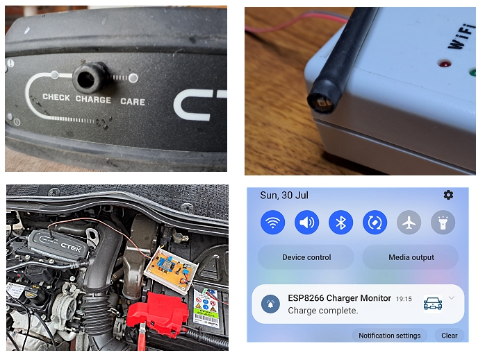
I keep a spare car battery in the garage which I like to charge now and then. To save me constantly checking the state of charge, this "Charger-Alert" monitors the "charging" LED on the battery charger and sends a notification to my mobile phone (via a third party website called PushSafer) when the charge is complete. As it proved impossible to open the charger to access the electrical connections, the Charger-Alert works by simply monitoring the charging LED on the charger using a photo-diode. The charger cycles through various charging modes during the charge so it wasn't possible to simply monitor the charging voltage.
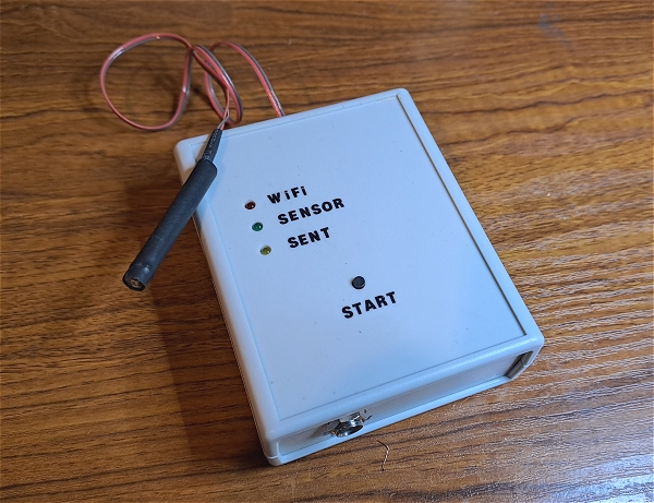
The photo diode is connected to the device through a short 2-core lead. I fitted the photodiode inside some shrink sleeving and super-glued a suitably-sized rubber grommet over the Charging LED on the charger. The photodiode can then be "plugged" into the grommet as required.
As I was testing what started off as a "novelty project", it became apparent that the device could be used as a more general "Alert" - A level alarm light coming on, for example. To make it slightly more versatile, the Alert is able to trigger the Notification when a light goes out (for example at the end of the battery charging) or when a light comes on (for example a High Level Alarm of some sort).
Whatever the application, the only constraint is that the device must be able to connect to your internet router in order to contact the PushSafer website..
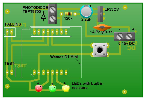
Circuit Diagram
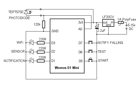
The simple circuit is built around a Wemos D1 Mini ESP8266.
I used three 5v 3mm LEDs with built in resistors but standard LEDs could be used with 220R resistors in series. The photodiode monitors the Charging LED on the battery charger and the SENSOR LED connected to output D2 simply 'echoes' if the charger's LED is lit.
When the SENSOR LED changes state (ie OFF to ON or ON to OFF), the sketch sends a notification request to PushSafer. If the request is accepted, the NOTIFICATION LED on output pin D1 lights.
The 'change of state' (ie the SENSOR LED going out or coming on) is determined by the FALLING jumper connected to input pin D7. With D7 LOW, a "falling" state (ie going from HIGH to LOW) will initiate the request to PushSafer.
When PushSafer accepts a notification request, it will respond with a "success" message and indicate the number of requests that are still available before a PushSafer subscription top-up is required. PushSafer will then send a Push Notification to the phone registered on your PushSafer Account. Your phone is just one device on your PushSafer Account but you can register several devices, such as a Windows PC, for example.
Upon receiving the "success" message, the NOTIFICATION LED on output pin D1 will light. When the number of available requests falls below a certain value (set at 10 in the sketch), the NOTIFICATION LED will flash.
To avoid wasting requests while testing, the TEST jumper connected to input D6 allows you to adjust the sketch and the
sensor sensitivity without sending an actual notification request to PushSafer. The built-in Blue LED on output pin D4 will flash
when the Charger-Alert is in TEST mode.
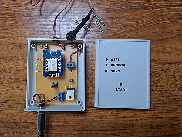
When the unit is powered up, it attempts to connect to your router. The WiFi LED on output pin D3 will begin to flash once the connection is established. The unit is now in a waiting state while you attach the photodiode sensor to the charger's LED. Once positioned, press the START button. The WiFi LED will now light solidly and the SENSOR LED will echo the Charger's LED.
The Wemos D1 Mini requires a 3.3 volt supply so I used an LF33CV very low dropout votage regulator. It provides for some flexibility in the power supply. Logically, the battery charger and the battery will be located close to each other so the power for the Charger-Alert can come from the battery being charged but it should run off a 5 volt lithium pack for some time if the battery isn't near the charger.
Components
- Wemos D1 Mini (Usually supplied with an assortment of 8-way Single In Line sockets).
- LF33CV Very low dropout regulator.
- 2.2uF electroliytic capacitor.
- TEPT5700 Photodiode.
- 1 x 120k Resistor.
- 3 x 3mm 3v LEDs (or standard LEDs with series 220R resistors).
- 2 x 2-way Pin Headers and jumpers.
- 2 x Connector blocks.
- 6mm tactile switch with 15mm long actuator.
- 2.1mm power socket.
- Hammond case: 1593BB.
Printed Circuit Board
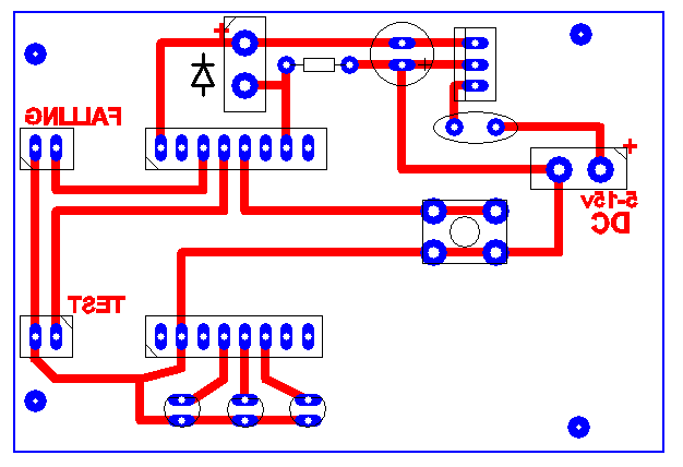
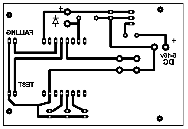
Download PCB Artwork in PDF format.
PushSafer
You will need to set up an Account at PushSafer. Once registered, you will be given a Private Key and a form in which to add "Devices" - normally your mobile phone. Each device will be assigned a unique Device ID. The Private Key and the Device ID need to be copied into the Arduino sketch (Lines 54 and 55).When you first register, you will be given a small quota of Notifications for free for test purposes. (It's a few years since I set up my Account so I can't remember exactly how may you get). However, an additional 1000 Notifications is currently 0.99 EUR (about £0.86 UK) and should last for ever in this simple application. Apparently, PushSafer will notify you when your Notifications are about to run out but I haven't reached that point yet after several years!
Setting up the Arduino IDE
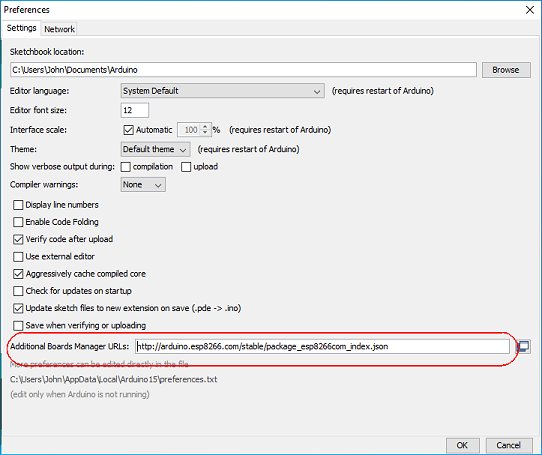
If you haven't used the ESP8266 in the Arduino environment before, it's necessary to install the ESP8266 Board definitions into the Arduino IDE.In the Arduino IDE, select File -> Preferences.
In the Additional Boards Manager URLs text box, enter: http://arduino.esp8266.com/stable/package_esp8266com_index.json then click the OK button.
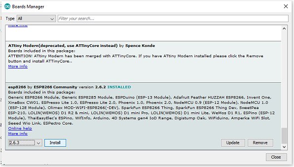
Select Tools -> Board -> Board Manager...
Wait for the platforms index to download then scroll down the list to esp2866 by ESP2866 Community and click Install.
Close the Arduino IDE.
Download and install an additional Arduino library: Arduino_JSON https://github.com/arduino-libraries/Arduino_JSON.
Copy the Arduino sketch below and paste it into the IDE. Select LOLIN (WEMOS) D1 R2 & Mini from the Tools | Board menu.
Edit lines 46 and 47 to your router SSID and password.
Edit lines 54 and 55 to your PushSafer Private Key and Device ID.
Lines 57 and 58 are the Title and Message that PushSafer will send in the notification to your phone. Edit these lines as appropriate.
You can also edit Line 60 to choose a suitable Notification Icon from the list on the PushSafer website.
There is some debugging code in the sketch so open the IDE's Serial monitor and set it to 115200 baud.
The Arduino Sketch