Lithium Battery Charger - Construction
Component Selection
The LT1510 is a buck/switcher type constant-current, contstant-voltage regulator running at 200kHz which can put more stress on its supporting components than a conventional 'linear' type regulator. Capacitors, in particular, need to handle relatively high ripple currents and at the higher frequency, 200kHz, than is normally associated with conventional power supply components.It's well worth reading both the LT1510 datasheet and the LT1510 design manual both of which go into great detail about component selection.
The following table lists the more critical (and/or less common) components. It's not a full list of all the parts used.
| CR1, CR3 | 1N5819 | |
| CR2 | 1N914 or 1N4148 | |
| L1 | 33uH 1.35A Inductor | ebay |
| C2 | 47uF 50v electrolytic capacitor | |
| C5 | 100uF 50v electrolytic capacitor | |
| R1 | 69.8k 0.1% | |
| R2a | 100k 0.1% | |
| R2b | 5.62k 0.1% | |
| Q1, Q2, Q3 | 2N7000 MOSFET | |
| Q4 | BS270 MOSFET | |
| FB | Ferrite Beads | ebay |
| IC1 | LT1510CN, LT1510CN#BPF, LT1510IN or LT1510IN#BPF | Linear Technology |
| Heatsink | 6.3mm x 20mm | Farnell, ebay |
| Regulator | uA7833CKCS (3.3v) Pin-compatible with the LM7805. | Farnell |
| IC2 | ATmega328 | With Arduino Bootloader |
| LCD | Nokia 5110 LCD | DealExtreme, ebay, etc |
| Current Sensor | Adafruit INA219 breakout borad | phenoptix, Adafruit |
| Fuse | 1.1A resettable fuse | CPC |
| Enclosure | Hammond Instrument Enclosure | Farnell |
| Connector | 42x42mm Speaker Box Connector | ebay |
| Fan | 25mm x 25mm x 10mm 0.08A cooling fan | ebay |
PCB Layout
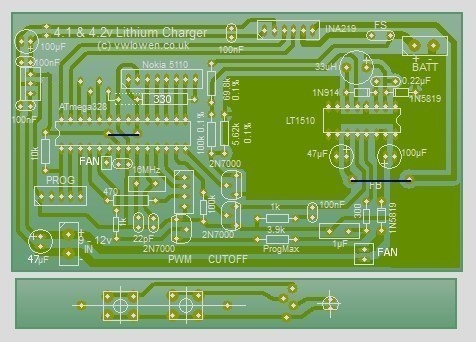
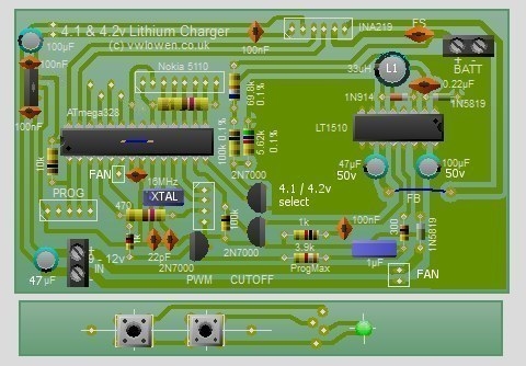
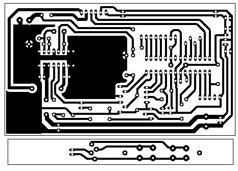
Download Circuit Wizard layout
The Nokia 5110 LCD
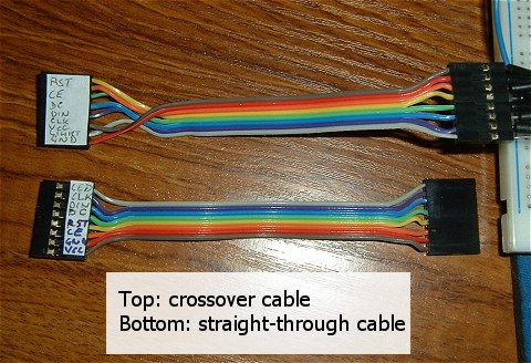
The Nokia 5110 LCD is available from several suppliers. Unfortunately, they all have different pinouts. In addition, some need a +ve supply for the backlight LED to light, others need ground.I always try to design my projects with the possible requirement to replace components but designing the PCB for whatever version of the display I may be able to get hold of in the future isn't straightforward.
Even re-defining the LCD's data pins in the ATmega software wouldn't take into account the two supply pins (Vcc and GND) or the backlight which makes designing a 'universal' PCB virtually impossible. I decided instead to design the PCB around one popular version (from DealExtreme) and different displays are catered for by crossing over the connections as required in the ribbon cable. It's not particularly pretty but it does serve its purpose.
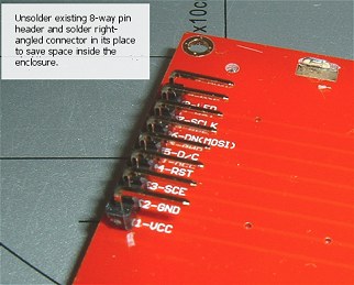
Most displays arrive with the 8-pin header already attached but some use the top row of connections, some the bottom row. When the header is fitted to the bottom row, it ends up very close to the 4-pin PCB socket/connector for the push button panel. To avoid any potential problems, I changed the 8-pin header on the display for a right-angled one. Alternatively, the header could be removed and replaced in the top row of connection holes.
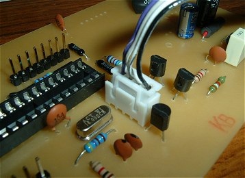
I also used a 4-way JST-XH connector for the cable to the push button panel, to increase the clearance, as it has a lower profile than the usual pin header.
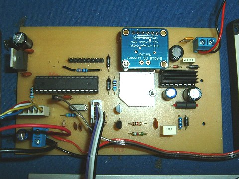
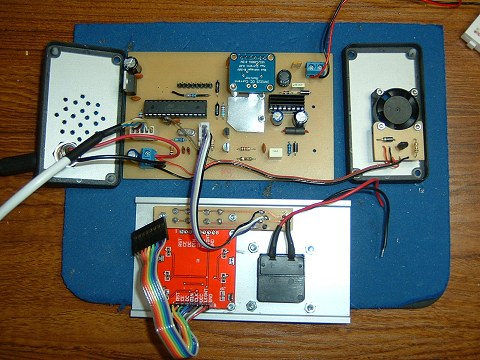
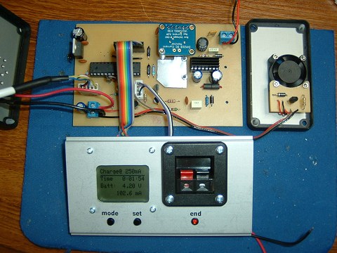
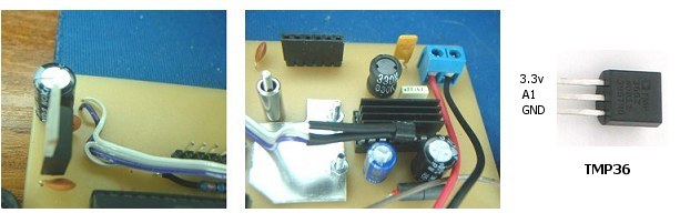
The Completed PCB
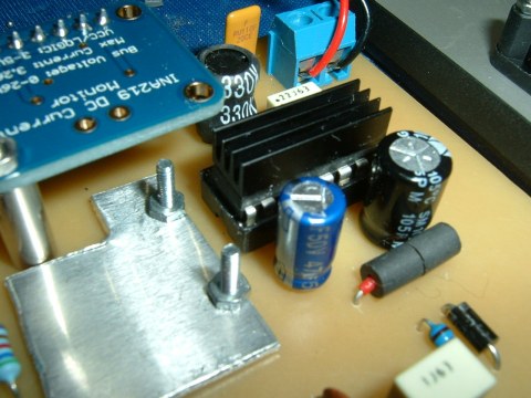
Various views of the completed PCB under final testing. The aluminium square bolted through to the PCB's copper ground plane is to assist with the cooling but I'm not sure if it makes much difference.I used sockets for the INA219 and the LT1510 because this is a prototype/development PCB. The LT1510 would probably run slightly cooler if it were soldered to the PCB.
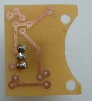
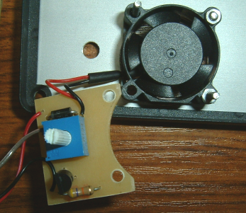
Fan - Speed Adjustment
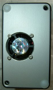
The PCB for the fan control is mounted on the fan itself. Most of the photos above show an earlier version. In the final version, I added a 10k preset for speed adjustment and the PCB is flipped over so the component side faces the enclosure end plate and the potentiomenter shaft protrudes through the end plate by about 1mm.
Fan - Update
As there are a few analogue inputs spare on the ATmega328, I decided to use one to monitor the temperature of the LT1510. As I already had a spare TMP36 in a TO-92 package in my spares box, it was simple enough to add. I drilled a couple of new 0.8mm holes in the main PCB near the 3.3 volt regulator to pick up the 3.3v supply to the sensor and I'd already provided solder pads for the unused analogue pins on the ATmega328 so I used input A1.I used a thin film of superglue to attach the sensor to the LT1510 heatsink.
Although it won't be very accurate, it's useful to have some idea of what the temperature is. The fan can now be switched on and off depending on the heatsink temperature.
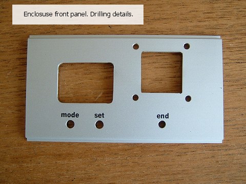
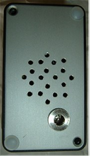
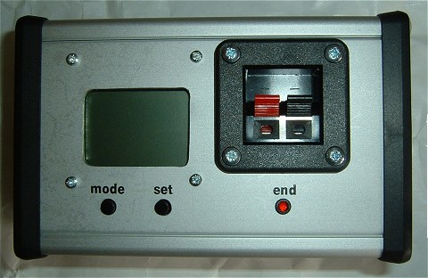
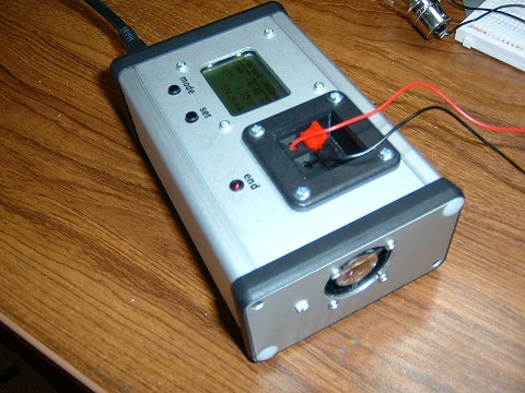
The Enclosure