The Calendar Registers
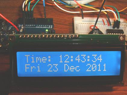
Adding the Date registers is really more of the same. In the sketch below, I've added arrays for the days of the week and the months. I've also added the code for the ByVac Serial LCD. This LCD uses the IASI-2 protocol so isn't communicated with in quite the same was as, for example, the Sparkfun display. I've written up details of the ByVac Serial LCD and a list of its Cursor positioning & control Commands.
I've combined some multi-line bits of code and moved repeated clock-setting code to a new function: updateClock(). There's very little error checking for invalid numbers so there are still a lot of improvements that could be made.
#include <SoftwareSerial.h>
#include <SPI.h>

#define rxPin 0
#define txPin 3

int chipEnablePin = 10;
int switchPin = 9;

// Set up meaningful arrays for day and month names for the LCD.

char* daynames[7] = {"Sun", "Mon", "Tue", "Wed", "Thu", "Fri", "Sat"};
char* monthnames[12] = {"Jan", "Feb", "Mar", "Apr", "May", "Jun",
                        "Jul", "Aug", "Sep", "Oct", "Nov", "Dec"};

// set up a new serial port for the ByVac serial LCD.
SoftwareSerial lcd(rxPin, txPin);

void setup() {
  lcd.begin(9600);                              // Initialize the ByVac Serial LCD.
  lcd.print("\r");
  lcd.print("\r");
  delay(500);

  lcd.print("ac1\r");                            // Clear display
  lcd.print("acc\r");                            // Cursor Off
  delay(1000);
  lcd.print("adTime:\r");

  pinMode(chipEnablePin, OUTPUT);                // Set the Chip Enable pin as output.
  pinMode(switchPin, INPUT);                     // Set the Time-Set switch as an inpit.
  Serial.begin(9600);
  digitalWrite(chipEnablePin, LOW);
  SPI.begin();                                   //  Set up the SPI library.
  SPI.setBitOrder(MSBFIRST);
  SPI.setDataMode(SPI_MODE1);

   // Initialize RTC Control Register.
  writeRegister(0x8f, B00000100); // bit 2 set = 1Hz (pin 7) ON
}

void loop() {
  if (digitalRead(switchPin) == HIGH) {           // Check if set-clock switch is pressed.
    setClock();
  }
  byte seconds = bcd2dec(readRegister(0x00), B1111); // Read the clock registers and convert BCD to decimal.
  byte minutes = bcd2dec(readRegister(0x01), B1111);
  byte hours = bcd2dec(readRegister(0x02), B11);

  byte day = readRegister(0x03) & B111;         // Day register is only bits 0, 1 and 2
  byte date = bcd2dec(readRegister(0x04), B11);
  byte month = bcd2dec(readRegister(0x05), B11);
  byte year = bcd2dec(readRegister(0x06), B1111);

  lcd.print("ac86\r");                           // ByVac LCD cursor to top row, column 6
  addZero(hours);                                // Print '0' to Serial Monitor and LCD if required.
  Serial.print(hours);                           // Print hours to Monitor and LCD.
  lcdPrint(hours);

  Serial.print(":");                             // Print ':' hrs:mins separator on Serial Monitor..
  lcd.print("ad:\r");                            // .. and LCD.

  addZero(minutes);                              // Repeat for minutes.......
  Serial.print(minutes);
  lcdPrint(minutes);

  Serial.print(":");
  lcd.print("ad:\r");

  addZero(seconds);                               // .... and seconds
  Serial.print(seconds);
  lcdPrint(seconds);

  Serial.print("  Date: ");
  lcd.print("acc0\r");                            // LCD cursor to 2nd row, column 0.

  Serial.print(daynames[day - 1]);                // Use 'day' value as index to 'daynames' array...
  lcd.print("ad");                                // .... (array starts at '0' index so 'day - 1'.
  lcd.print(daynames[day - 1]);
  lcd.print(" \r");
  Serial.print("  ");

  addZero(date);
  Serial.print(date);
  lcdPrint(date);

  Serial.print("/");

  Serial.print(month);                             // Print month on Serial Monitor
  lcd.print("ad ");
  lcd.print(monthnames[month-1]);                  // Print monthname on LCD.
  lcd.print(" \r");

  Serial.print("/");

  Serial.print("20");                              // Assume always year 20xx.
  lcd.print("ad20\r");
  Serial.println(year);
  lcdPrint(year);
  delay(1000);
}

void lcdPrint(byte value) {                         // Function to print value on LCD
  lcd.print("ad");
  lcd.print(value);
  lcd.print("\r");
}

void addZero(byte value) {
  if (value < 10) {
    Serial.print("0");
    lcd.print("ad0\r");
  }
}

byte readRegister(byte Reg) {
  digitalWrite(chipEnablePin, HIGH);
  SPI.transfer(Reg);
  byte getByte = SPI.transfer(Reg);
  digitalWrite(chipEnablePin, LOW);
  return getByte;
}

void writeRegister(byte Reg, byte value) {
  digitalWrite(chipEnablePin, HIGH);
  SPI.transfer(Reg);
  SPI.transfer(value);
  digitalWrite(chipEnablePin, LOW);
}

byte bcd2dec(byte value, byte mask) {
  byte units = value & B00001111;            // For the units, we only want bits 0 to 3 so mask off the rest.
  byte tens = ((value >> 4) & mask) * 10;    // Shift the top 4 bits to the right, 4 times and mask unwanted bits.
                                             // Then multiply by 10 to make decimal 'tens'.
  return  tens + units;                      // Return the sum.
}

byte dec2bcd(byte value, byte mask) {
  byte bcdHigh = ((value / 10) << 4) & mask; // Integer divide by 10 to get the mantissa then shift the result to
                                             // the left most significant bits. mask off unwanted bits.
  byte bcdLow = value % 10;                  // Modulus divide by 10 to get the remainder...
  return bcdHigh | bcdLow;                   // and bitwise OR them to assemble the complete BCD byte.
}


  /* ================================================================================
   * setClock() and getSerialInput() are kludges to test
   * the concept of setting the clock's registers.
   * ================================================================================

void setClock() {
  updateClock("Hours: ", 0x82, B00110000);
  updateClock("Mins: ", 0x81, B11110000);
  updateClock("Seconds: ", 0x80, B11110000);
  updateClock("Day (2 digit number): ", 0x83, B0);
  updateClock("Date: ", 0x84, B00110000);
  updateClock("Month: ", 0x85, B00110000);
  updateClock("Year: ", 0x86, B11110000);
  Serial.print("\n");
  while (digitalRead(switchPin) == HIGH);
}


void updateClock(char* prompt, byte reg, byte mask) {
  Serial.print("\n");
  Serial.print(prompt);
  int val = getSerialInput();
  Serial.print(val);
  val = dec2bcd(val, mask);
  writeRegister(reg, val);
  Serial.flush();
}


  /* Inputting a character string as a number on the Serial Monitor and returning it to the Arduino
   * isn't straightforward because the Arduino will only accept a byte at a time. This function waits
   * until two characters have been entered on the Serial Monitor, then contructs a 2-digit decimal
   * number and returns it. */


int getSerialInput() {
  int num = 0;
  while (Serial.available() < 2);           // Wait until 2 characters are in the buffer.

  char ch = Serial.read();
  if (ch >= '0' && ch <= '5')               // First character must be between '0' and '5'
    num = (ch - '0') * 10;                  // First character is decimal 'tens'

  ch = Serial.read();
  if (ch >= '0' && ch <= '9')
    num = num + (ch - '0');                 // Add decimal 'units'

  return num;
}