ESP8266 Temperature Plotter
Summary
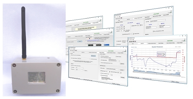
This is a simple project to monitor the temperature at a remote location and plot it on a chart (or graph) in a Windows application. The resulting chart is also available anywhere with an internet connection courtesy of a web server built into the plotter application.The application has adjustable alarm setpoints for high and low temperature, low battery voltage and loss of signal between the sender and the router and can (optionally) sound an alarm between set times of the day and/or send you an email and a notification to your mobile.
The project can be divided into two distinct parts: The temperature monitoring hardware (the ESP8266 Sender) and the Windows application which plots the data, acts as a web server and handles the alarms (the ESP8266 Plotter).
The Sender and the Plotter are designed to work together as a pair and - unusually for ESP8266 projects - the router-specific connection details (such as the router ssid and its WiFi password) are not hard-coded into the esp8266 sketch. Instead, the ESP8266 Sender is pre-programmed with a once-only "skeleton" sketch and it is then able to request the full router-specific configuration settings, via USB, from the ESP8266 Plotter application without requiring the original Arduino IDE programming environment.
Once the ESP8266 Sender has the router-specific details, the configuration will be retained just as though it had been hard-coded but with the ability for the ESP8266 Plotter to easily upload new settings should the Sender need to connect with a different network or change the WiFi password, for example. This also makes it easy to change the sleep interval between taking temperature measurements, change the resolution of the temperature sensor or change the ID of the specific ESP8266 Sender.
The initial configuration and subsequent router-specific details (password and SSID) are, of necessity, passed to the ESP8266 Sender using a USB port but the WiFi timeout, the sleep interval and the temperature resolution can also be updated over WiFi. The changes are initiated in the Plotter application and will be automatically uploaded by WiFi and will take effect after the next sleep interval.
The ESP8266 Plotter application is a stand-alone Windows program available as a freeware download so this article will concentrate on building the hardware - the ESP8266 Sender - because the ESP8266 Plotter application has a built-in comprehensive Help file..
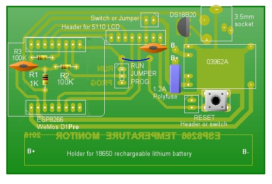
The Circuit of the ESP8266 Sender
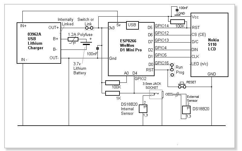
The circuit consists primarily of the ESP8266 Wemos D1 Mini Pro module, a Dallas DS18B20 temperature sensor and a 03962A lithium battery charger module. I added a Nokia 5110 LCD display but this obviously increases the Sender's current consumption so, if absolute maximum battery life is required, the display can be omitted. The Arduino sketch has been written to easily add or remove the display from the code. In fact, the LCD can simply be disconnected without changing the code and the sketch still runs without any problems.
The DS18B20 temperature sensor is connected in 'parasitic' mode to the ESP8266 input D4 (GPIO2) and the pull-up resistor on its data pin (pin 2) is a fairly low value because the 3.3 volt supply is near the sensor's lower operating voltage limit (3.0v).
I've incorporated a 3.5mm jack socket so an external DS18B20 sensor can be used instead of the internal one. This allows the sensor to be placed in difficult locations, such as a refrigerator or freezer, for example and increases the accuracy because the internal sensor inevitably reads slightly high due to the small amount of heat generated in the enclosure - especially when the battery is being recharged with the built-in charger.
The USB socket on the WeMos D1 Mini Pro is obviously required to upload the once-only skeleton Arduino sketch but it is also used to configure the router-specific settings uploaded from the Sender. The 5 volt output from the WeMos D1 Mini Pro (which is available when the USB cable is connected) is used to power the 03962A charger module so its USB socket doesn't need to be accessible as it is not used.
 The battery voltage is measured at the WeMos D1 Mini Pro's only analogue input, A0, which isn't actually connected internally to the ESP8266's analogue pin:
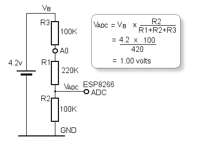
Instead, A0 is connected to the top end of an on-board voltage divider, designated R1 and R2 in the WeMos D1 Mini Pro schematic. The values of R1 and R2 are chosen so that 3.2 volts applied to A0 results in exactly 1 volt at the ESP8266's "true" ADC input - 1 volt being the ADC's maximum input voltage.
As we want to measure the lithium battery, with an on-charge voltage of 4.2 volts, we need to modify the voltage divider by adding an additional resistor (R3) as shown to the left.
Now the maths is such that 4.2 volts at the top end of R3 results in exactly 1 volt at the ADC input. Due to tolerances in the on-board resistors and the external 100K resistor, some tweaking of the code may be necessary to get the indicated voltage to match the actual, measured, battery voltage.
After much testing over nearly 12 months, the ESP8266 WeMos D1 Mini (Pro) modules seem to tolerate 4.2 volts on their Vcc pin.
A resettable polyfuse is included in the battery circuit as I always prefer to use a fuse when a lithium battery is used. The battery is permanently connected to the charger module (via the polyfuse) but the PCB layout allows for a power switch in the positive supply to the ESP8266, the DS18B20 sensor and the Nokia 5110 display. Current consumption while the ESP8266 is asleep is around 75µA including that taken by the display (which shows data even while the ESP8266 is asleep) so a power switch could reasonably be considered optional.
The ESP8266 spends most of its time in "deep sleep" to conserve battery. It wakes at the specified interval by taking output D0, (GPIO16) low. In normal 'run' mode, this output is connected to the ESP8266's RESET pin, waking itself up and restarting the sketch.
With the WeMos D1 mini modules that I've tested, it seems the 'Pro' version will accept programming even when D0 and RST are connected but the "non-Pro" version will not, so I've included a jumper on the PCB which can be removed to program the non-Pro version.
When the ESP8266 is in deep sleep mode, its IO pins are floating (or tri-state). This leaves the Nokia 5110 RST pin in an indeterminate state so, sometimes the display would be blank when the ESP8266 was asleep but other times it would show the display. The 100K resistor between Vcc and the Nokia RST pin ensures the pin is in a known state (HIGH) and the display will always be shown.
In order to request configuration data from the ESP8266 Plotter application, the RESET button overrides the sleep cycle and forces a restart.
During the restart sequence, the Sender interrogates the Plotter. If it gets a response (meaning the Plotter has opened a USB COM port to the Sender) , the Sender invites the Plotter to upload the configuration settings. In practice, this means that a RESET button should, ideally, be accessible from outside the Sender's enclosure. However, if a WeMos D1 Mini Pro version is used, it can be woken up/reset via the USB connection from the Plotter application so there should be no need to for the RESET button to be accessible in that case.
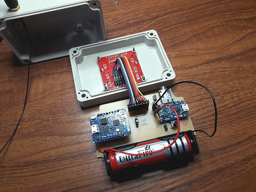
Construction
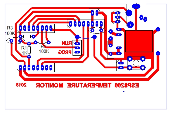
Download the PCB layout in PCB Wizard format.
PCB artwork as actual-size PDF
Arduino Sketch
To program the ESP8266 using the Arduino IDE, you need to install the ESP8266 Board Package but first, make sure your Arduino IDE version is 1.6.4 or later. The Arduino IDE version is shown in the Arduino IDE title bar.Open the Arduino IDE and select File | Preferences. Near the bottom of the window that opens, copy and paste the following URL into the Additional Boards Manager URLs text box: http://arduino.esp8266.com/stable/package_esp8266com_index.json and click OK.
Next, ensuring you have an internet connection, select Tools | Board: | Boards Manager. Scroll down to the esp8266 by esp8266 Community option and click Install. Wait while the ESP8266 Board Package downloads and installs.
Restart the Arduino IDE and, under Tools | Board: select the WeMos D1 board.
Copy the following sketch and paste it into the Arduino IDE. It should compile without error. Connect the WeMos D1 Mini Pro board via USB, selelct the appropriate Port under Tools | Port and upload the sketch in the usual way. If you're using the non-pro version of the WeMos board, make sure the link between RST and D0 (GPIO16) is NOT fitted during the upload.
/*  This ESP8266 Temperature Sender Sketch is written to work exclusively with the "ESP8266 Plotter"
 *  Windows software at http://vwlowen.co.uk/arduino/esp8266-temperature-logger/esp8266-plotter.htm
 */

#include <EEPROM.h>
#include <SPI.h>
#include <Wire.h>
#include <ESP8266WiFi.h>
#include <ESP8266HTTPClient.h>

#include <Adafruit_GFX.h>
#include <Adafruit_PCD8544.h>  // https://github.com/bbx10/Adafruit-PCD8544-Nokia-5110-LCD-library/tree/esp8266


/* Temp Sensor */
#include <OneWire.h>
#include <DallasTemperature.h>

/*
 * Define here whether to use the Serial monitor to DEBUG the results and/or
 * whether a Nokia 5110 LCD is installed.
 */

#define DEBUG false        // If set to 'true' sends debugging info to the Serial monior.

#define LCD true          // Define whether Nokia 5110 display is installed.

#define CONTRAST 60       // Adjust the LCD contrast here.

//     WeMos GPOI  - These Defines allow us to use WeMos D? pin numbers instead of x-referencing GPOI numbers.
#define D0  16
#define D1  5
#define D2  4
#define D3  0
#define D4  2
#define D5  14
#define D6  12
#define D7  13
#define D8  15


// Set up the pin that the temperature probe is connected to.
OneWire oneWire(D4);

// Define the temperature sensor object
DallasTemperature sensors(&oneWire);


//Adafruit_PCD8544 display = Adafruit_PCD8544(CLK, DIN, D/C, CS, RST);
//Adafruit_PCD8544 display = Adafruit_PCD8544(5, 4, 13, 12, 14);            // GPIO numbers

Adafruit_PCD8544 lcd = Adafruit_PCD8544(D1, D2, D7, D6, D5);                // WeMos Mini pin numbers


float volts = 0.0;                    // Define and initialise measured values.
float temperature = 0.0;
unsigned long timeToSend;
unsigned long timeUsed;

struct {
    char serverIP[25] = "";           // Set up a structure to store the server's IP address and Port number,
    char ssid[25] = "";               // the router's SSID and
    char pass[25] = "";               // Wifi access password.
    char deviceId[11] = "";           // Set a 'Device ID' so the server knows which ESP8266 is sending data.
    char timeout[3] = "";             // Connection timeout.
    char resolution[3] = "";          // Set Dallas temperature sensor resolution.
    char sampleStr[11] = "";          // Set the interval for the ESP8266 to wake and send data.
} data;


// Convert raw analogue readings (0 to 1023) to 0 to 4.2 volts

double mapf(double val, double in_min, double in_max, double out_min, double out_max) {
    return (val - in_min) * (out_max - out_min) / (in_max - in_min) + out_min;
}


void setup () {
  timeToSend = millis();
  Serial.begin(9600);

  uint addr = 0;                                  // EEPROM start address

  EEPROM.begin(125);                              // Initialize flash memory for EEPROM use.

  if (LCD) {                                      // If LCD is defined as 'true'  set up the Nokia display.
    lcd.begin();
    lcd.setContrast(CONTRAST);
    lcd.clearDisplay();
    lcd.display();
    lcd.setTextSize(1);
    lcd.setTextColor(BLACK);
  }

  Serial.print("STARTtestCheckENDtest");          // Send a test string to the Windows executable...
  delay(100);                                     // Allow chance for it to reply.

  if (Serial.available() > 0) {                   // If there's a response, the USB cable is connected and the
     if (Serial.readString() == "OK") {           // Com Port is open.

       if (LCD) {
         lcd.println(" Waiting for  configuration from plotter.");
         lcd.println("");
         lcd.print("Press 'Upload'");              // Prompt user to send the configuration from the ESP8266 Plotter.
         lcd.display();
       }

       Serial.flush();                             // Clear the serial buffer.
       Serial.setTimeout(200);                     //
       while (Serial.available() == 0);            // Wait for "SOH"-delimited data string from Windows application.
                                                   // "SOH" (0x01) is not a keyboard char so won't be be used
                                                   // in password or device Id.

       if (Serial.available() > 0) {
         Serial.readBytesUntil(0x01, data.serverIP, 25);   // Read each value from 0x01-separated string into data structure...
         Serial.read();                                    // ... skip delimiter.
         Serial.readBytesUntil(0x01, data.ssid, 25);
         Serial.read();
         Serial.readBytesUntil(0x01, data.pass, 25);
         Serial.read();
         Serial.readBytesUntil(0x01, data.deviceId, 11);
         Serial.read();
         Serial.readBytesUntil(0x01, data.timeout, 3);
         Serial.read();
         Serial.readBytesUntil(0x01, data.resolution, 3);
         Serial.read();
         Serial.readBytesUntil(0x02, data.sampleStr, 11);

         EEPROM.put(addr, data);                   // Write the data structure to EEPROM.
         EEPROM.commit();                          // Required command with the ESP8266.

         data = {};                                // Clear the data structure so we can confirm we're re-populating
                                                   // it from the EEPROM...
         EEPROM.get(addr, data);                   // Retrieve data from EEPROM and...

                                                  // ... echo it back to the Windows application.
         char sep = 0x01;

         String OutList = "START" + String(data.serverIP) + sep + String(data.ssid) + sep + String(data.pass) + sep +
                                  String(data.deviceId) + sep + String(data.timeout) + sep + String(data.resolution) + sep + String(data.sampleStr) + "END";
         Serial.print(OutList);
      }
    Serial.flush();
    }
  } else {                                                      // The Windows executable isn't connected so retrieve
                                                                // the configuration settings from the ESP8266 EEPROM.
     EEPROM.get(addr, data);
  }

  WiFi.begin(data.ssid, data.pass);                             // Connect to the WiFi asap. Other code can execute while
                                                                // WiFi is connecting.

  int timeout = String(data.timeout).toInt();
  int sample = String(data.sampleStr).toInt() * 60;             // Convert sampleStr to an integer and convert to seconds.

  if (DEBUG) {
    Serial.println(); Serial.println();
    Serial.println("ServerIP: " +  String(data.serverIP));      // Echo values back to Serial Monitor (if DEBUG is true).
    Serial.println("ssid: " + String(data.ssid));               // Serial Monitor cannot be open at the same time
    Serial.println("pass: " + String(data.pass));               // as the Windows executable is connected.
    Serial.println("DeviceId: " + String(data.deviceId));
    Serial.println("Timeout: " + String(data.timeout) + " seconds");
    Serial.println("Resolution: " + String(data.resolution));
    Serial.println("Sample: " + String(sample) + " seconds");
    Serial.println("");
  }

  /*
   * Votage divider on Analog pin is (100k + 220k) over 100k which is 100 / (100 + 220 + 100)
   * or 100 / 420  so 0 to 4.2 volts equates to 0 to 1023 raw analog read.
   */

  pinMode(A0, INPUT);
  float raw = 0.0;
  raw =  analogRead(A0);                            // While WiFi is connecting, read analogue value.
  volts = mapf(raw, 0.0, 1023.0, 0.0, 4.20);        // Convert raw analogue (0 to 1023) to 0 to 4.2 volts.


  if (LCD) {
    lcd.clearDisplay();
    lcd.print("Connecting...");
    lcd.display();
  }
  float i = 0.0;
  while (WiFi.status() != WL_CONNECTED) {
     i = i + 0.1;
     delay(100);

      if (i > String(data.timeout).toInt()) {
       if (LCD) {
         lcd.println();
         lcd.print(" Connect Error");
         lcd.display();
       }
       ESP.deepSleep(sample * 1000000);                 // Connection failed so Sleep
     }
  }

  if (DEBUG) {
    Serial.print("Connected to ");
    Serial.println(WiFi.SSID());
    Serial.print("IP address: ");
    Serial.println(WiFi.localIP());
  }


  int res = String(data.resolution).toInt();
 // Set up the temp sensor and get an initial value
  sensors.begin();

  // Set resolution to 9-12bit,
  //  9 bit = 0.5*c    @ 93.75ms
  // 10 bit = 0.25*c   @ 187.5ms
  // 11 bit = 0.125*c  @ 375ms
  // 12 bit = 0.0625*c @ 750ms
  sensors.setResolution(res);        // Higher resolution is potentially more accurate but keeps the ESP8266 awake for longer.
  sensors.requestTemperatures();

  temperature = sensors.getTempCByIndex(0);

  String tempS;
  tempS = String(temperature);

  int rssi = WiFi.RSSI();


  if (DEBUG) {
    Serial.println("Temperature: " + String(temperature));
    Serial.println("Battery: " + String(volts, 3));
  }

  // Check if the WiFi is connected
  if (WiFi.status() == WL_CONNECTED)  {
    //Declare an object of class HTTPClient
     HTTPClient http;

     String wifiUpdate = "";

     http.begin("http://" + String(data.serverIP) + "/update");

     int httpCode = http.GET();
     if (httpCode > 0) {
      wifiUpdate = http.getString();                  // Send a dummy GET request to the ESP8266 Plotter's server.

      if (DEBUG) {                                    // If the server responds with 'UPDATE', it will also send
        Serial.println(wifiUpdate);                   // the temperature resolution and Sample interval values
      }                                               // in the format: 'UPDATE{resolution}!{interval}%{timeout}'

      if (wifiUpdate.substring(0, 6) == "UPDATE") {
        String resStr = wifiUpdate.substring(6, wifiUpdate.indexOf('!'));
        String sampStr = wifiUpdate.substring(wifiUpdate.indexOf('!')+1, wifiUpdate.indexOf('%'));
        String timeoutStr = wifiUpdate.substring(wifiUpdate.indexOf('%')+1);

        resStr.toCharArray(data.resolution, resStr.length() +1);
        sampStr.toCharArray(data.sampleStr, sampStr.length() +1);
        timeoutStr.toCharArray(data.timeout, timeoutStr.length() +1);

        EEPROM.put(addr, data);                   // Write the data structure to EEPROM.
        EEPROM.commit();                          // Required command with the ESP8266.

        EEPROM.get(addr, data);                   // Check data is written to EEPROM.

        res = String(data.resolution).toInt();
        sample = String(data.sampleStr).toInt() * 60;
        timeout = String(data.timeout).toInt();

        if (DEBUG) {
          Serial.println("New Timeout: " + String(data.timeout));
          Serial.println("New Resolution: " + String(data.resolution));
          Serial.println("New Sample: " + String(sample) + " seconds");
        }
      }
    }
    http.end();

    // Specify request destination, including your GET variables

    timeUsed = millis() - timeToSend;

     http.begin("http://" + String(data.serverIP) +
                            "/apage.htm?id=" +
                            String(data.deviceId) +
                            "&leftaxis=" + tempS +
                            "&rightaxis=" + String(volts) +
                            "&rssi=" + String(rssi) +
                            "&time=" + String(timeUsed));

    // Send the request
      httpCode = http.GET();

    // Check the returning HTTP code
     if (httpCode > 0) {
      // Get a response back from the server
       String payload = http.getString();
      // Print the response
       if (DEBUG) {
         Serial.println(payload);
       }
     }

    // Close the HTTP connection
     http.end();
  }

  if (LCD) {
    String ssid = WiFi.SSID();
    if (ssid.length() > 13 ) {                     // Limit length of WiFi SSID to fit LCD screen.
      ssid = ssid.substring(0, 11) + "..";       // Maximum 13 characters, else 11 characters plus '..'
    }

    lcd.clearDisplay();
    lcd.println(ssid);

    lcd.println(WiFi.localIP());
    lcd.print(rssi);
    lcd.print("dBm");

    lcd.setCursor(52, 16);
    lcd.print(volts, 2);
    lcd.println("v");

    lcd.print("S: ");
    lcd.print(sample / 60);
    lcd.println(" T: " + String(data.timeout));

    lcd.print("ID: ");
    lcd.println(String(data.deviceId));

    lcd.print("Temp ");
    lcd.print(temperature, 1);
    lcd.print(" (");
    lcd.print(res);
    lcd.print(")");

    lcd.display();
 }


  // Sleep
  if (DEBUG) {
    Serial.println("ESP8266 in sleep mode");
  }

  ESP.deepSleep(sample * 1000000);

}

void loop() {
}