Arduino USB-RS232 Lead
In some respects, the Picaxe scores here because, although it needs a one-off purchase of a special "USB programming lead", actual projects using Picaxe hardware require nothing more than a 3.5mm pcb-mounted stereo jack socket through which to accomplish the in-circuit programming of the micro-controller.
In the Arduino system, every board (UNO, Mega 2560, Nano, etc) sports its own USB-to-RS232 converter chip. The advantages are that it allows the use of a standard off-the-shelf USB-A to USB-B patch lead and the 5 volt power for the project can come from the computer USB port.. The disadvantage becomes more obvious when building "stand-alone" Arduino-based projects.
Whether to include a USB-RS232 converter (such as the Sparkfun Breakout Board for FT232RL) or to program the ATmega chip externally before adding it to the project.
Many experienced Arduino users have built external programmers or use an external USB-to-RS232 converter and connect to the ATmega with TTL-Level RS232 signals.
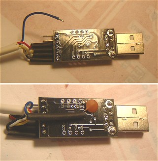
There are quite a few USB stick-sized converters available. The photos below show ones I bought off ebay.
They're also available from ByVac.
Most of these USB-RS232 converters use the CP210x USB to UART Bridge VCP Drivers from Silicon Labs. Whichever converter you use, I'd advise that you download the latest drivers. I
spent wasted several hours trying to get a converter working with older drivers that worked perfectly with a
converter lead I'd built some time ago. (And, yes, the older converter still worked with the new drivers!)
At the time of writing, the current boards from ByVac have a solder jumper to select the output voltage available from the board. I suggest setting this to 3v3 because the ATmega328 will run & program happily at this voltage and any other components in your project should be 'safe' at this voltage - even if they normally use 5v to function. You might damage any 3v3 items in your project if you leave the jumper at 5v and use it to supply power to your project.
In practice, the output current available from these converters is usually very limited so I nearly always leave the Vcc connection from the converter lead disconnected and power the project using its own supply.
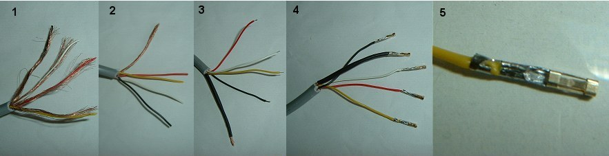
- I used about a 1 metre length of four-core individually screened audio cable. Strip about 30mm of the outer insulation.
- Unravel the individual screening braids and twist them into a pigtail clear of the inner conductors. Cut off some of the braid as using
it all makes the pigtail too thick.
- The choice of plug at the "project end" of the lead is a personal choice. To be able to use the "Auto-Reset" circuit, at
least 4 connections are needed (RX, TX, RESET and Ground). The converter board provides a convenient 5v supply from the
computer USB port so, to make use of that to power the project, a total of 5 connections are needed.
There seems little point in choosing an expensive plug and socket arrangement (the Picaxe scores here with it's inexpensive 3.5mm jack plug!) so I opted for a simple 5-way header pin and socket arrangement. Strip and tin about 1.5mm of each conductor and insulate the pigtail with some heatshrink tubing. Slide some larger heatshrink tubing over the outer sheath so that it can be slid back towards the plug shell once the soldering is complete (see photo 9).
- Crimp on the header plug female pins using long-nosed pliers and then solder inside.
- Don't use too much solder so as to keep the pin "slim". Fold the 'wings' over onto the insulation to provide some mechanical
support.
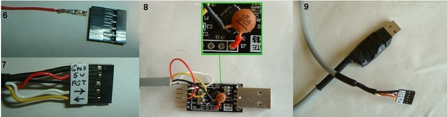
- The pins should slide easily into the header plug shell and 'click' into position.
- I added a paper label to remind me which way to plug it into the male header pins on the project. I used arrows to
indicate TX and RX and note that RST, -> and <- correspond to pins 1, 2 and 3 on the ATmega328.
- Strip the other end of the cable and solder to the appropriate pins on the converter. Note that, on the converter board I used, the
labels for the RXD and TXD pins correspond directly with the ATmega RX and TX pins. It was NOT necessary to cross over the RX and TX pins
as it is with other converter boards. Other boards may be different so try both ways if it doesn't work.
Solder one side of a 100nF capacitor to the DTR pin on the board and connect the RESET lead to the other side. Make sure all the connections are well insulated and wrap the entire board with insulationg tape. Use heat-shrink tubing where appropriate to provide support and insulation.
The photos above and below show an earlier board which didn't bring the DTR connection out to a pin so the capacitor has to be soldered directly to the board. Boards sold by ByVac seem to bring the DTR Signal out to a pin but you still need the 100nF capacitor.
Of course, it would be neater to omit the capacitor and include it in your project instead but I think it's easier to fit the capacitor here in the programming lead (once) rather than having to remember to include one in every project. If you do include one in a project, the two 100nF caps in series still provides a good enough signal to RESET the ATmega328.
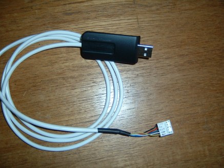
Update
When a USB "shell" became available (from a faulty video-USB converter) I decided to make a second version. I think this one is much neater!Not visible in the photos, I fitted a small cable tie to the cable just inside the USB "shell" to stop the cable being pulled. I didn't use screened cable this time. Instead I used 6-core house-alarm cable (only 5 cores are used). I kept the length to just under 1 metre and it seems to function reliably despite not being screened.