The Vacuum Fluorescent Display
Despite the fact that it's been around for a long time, the vacuum fluorescent display (VFD) is still a very attractive type of display. It's viewable in bright light but is easily dimmable for comfortable viewing in the dark. It has the versatility of a Liquid Crystal Display in that its illuminated elements can be formed into any shape and it doesn't need a backlight.
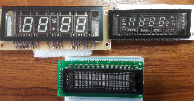
This photo shows three typical types of VFD. The top two have the familiar 7-segment numeric digits and include some extra elements specific to the device they're intended for. The one on the right seems to be for a clock radio with timer and sleep functions. The one on the left is probably be for a temperature-controlled device. I picked them both up off eBay for less than 5 UKP each. Despite their obvious differences, they have one thing in common: They are "bare" displays without any control circuitry.
The display at the bottom of the photo is different. Instead of the 7-segments to form the characters, it uses a 7x5 matrix of "pixels" for each character and is, therefore, alpha-numeric. It's identical in behaviour to a 16x2 LCD alpha-numeric display. In fact, the one shown here comes equipped with all the necessary voltage and control logic and is fully compatible with the Arduino's Liquid Crystal Display Library. It's also about six times more expensive than the top two!
How The VFD Works
Futaba Vacuum Fluorescent Display Application Note
The VFD consists of three basic elements all contained in a glass enclosure from which the air has been removed:
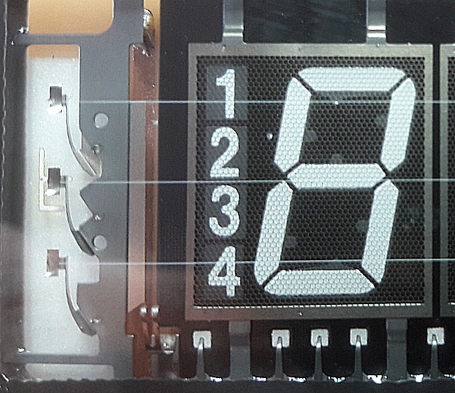
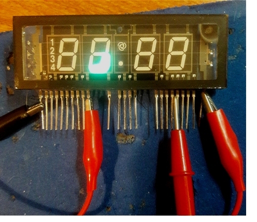
Stretched across the front of the enclosure, just behind the glass, are several fine wires connected in parallel. In the close-up above, there are three such wires. In the "clock radio" display and the 16x2 matrix display, in the top photo, you can just make out five wires. These wires - the filament - are coated with barium, strontium and calcium oxides which emit a cloud of electrons when a low voltage - typically between 3 and 5 volts - is applied to the ends. Electrically, it's function is similar to the heated cathode in a thermoinic valve (vacuum tube) and is comparable with a 7-segment LED display's cathode in a common-cathode LED.
Behind the filament is a series of fine mesh grids. There is one grid for each group of segments. In the VFD on the left of the top photo (and in the close-up above), the first grid covers the vertical row of numbers 1 2 3 4 and the first 7-segment digit. The second grid covers the second digit, the third grid covers the decimal point and the fan symbol, and so on.
The segments forming the digits and the symbols are positioned as a third layer behind the grids and are coated with material, such as zinc oxide, which fluoresces when bombarded with electrons from the filament. The operation is as follows:
If a positive voltage is applied to a grid, the electrons from the filament will be attracted towards the grid and, if a positive voltage is also applied to specific segments of a 7-segment digit and/or the symbols, the electrons will be accelerated through the grid and hit those segments which will fluoresce.
The positive voltage on the grid and the segmens needs to be significant, relative to the filament, and can be in the order of 25 or 30 volts. The higher the voltage, the more electrons will hit the segments and the brighter they will glow but the greater the current that will be drawn from the higher voltage supply.
To block the electrons and turn off a digit, the positive voltage is removed from both the grid and the segments. Ideally, to ensure the electrons are fully repelled, it's recommended that a small negative voltage (relative to the filament) is applied to the grid and the segments. With filaments powered by AC, this is usually accomplished by taking the grids and segments to 0v (ground) and biasing the filament a couple of volts positive with respect to ground.
In practice, most hobby projects simply switch the grid and the segments to 0v without any additional positive bias on the filament and that is sufficient to stop the electrons being attracted to the grid and the segments.
In a display with multiple digits, it's obviously not practical to bring out every single segment to its own connection pin, so the display is driven in a multiplexed fashion, very similar to multi-digit 7-segment LED displays. The appropriate segments for a particular digit and its grid are activated rapidly for each digit in sequence.
Design Consideraions
There are a number of factors to consider when designing an Arduino project which uses a Vacuum Fluorescent Display.The high voltage for the grids and the segments needs to be kept away from the Arduino so, obviously, this volatge can't be switched directly. The simplest scheme is to use discrete transistors - 7 for the segments and one for each of the digits. Unless two transistors are used for each swich, this has the efect of reversing the "logic" such that a HIGH at the transistor base, switches OFF the collector voltage.
There are driver ICs specifically designed to switch VFDs which don't reverse the logic and tend to be a bit easier to lay out on a PCB because all the associated biasing resistors are contained within the IC, so that's what I've used in this project.
 The second factor concerns the filament voltage.
As noted above, the brightness of the segments depends on their voltage above the filament voltage. The greater the voltage difference, the brighter the segment.
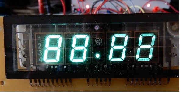
The photo on the left shows the effect of powering the filament with a DC voltage. Because the left hand end of the filament is connected to 0v and the right hand end is connected to +3v, the segment-to-filament voltage difference is greater at the left hand end of the display and the corresponding digit is noticeably brighter.
For this reason, the filament is usually fed with an AC voltage. With the polarity constantly changing, neither end of the display is favoured over the other.
Suitable low voltage transformers are difficult to find and add complications to the project's power supply, but there's a work-around with the Arduino. By feeding the filament from a pair of IO pins, one
HIGH and one LOW, and alternately switching, the polarity of the filament can be switched hundreds of times a second and the luminence gradient
is eliminated. However, care needs to be taken with the current consumption of the filament. Individual ATmega328P IO pins can handle a maximum of 40mA or 200mA total
for all pins.
Some displays may use less than 40mA in wich case it may be safe to feed the filament directly from two IO pins provided the filament voltage isn't exceeded. According to the datasheet for the display I've used in the clock, the filament takes between 67mA and 83mA. It's difficult to measure accurately as it's a square wave voltage but my display seems to be around 75mA. Although I have run the filament directly from two ATmega328P pins, it's obviously exceeding the pins' rating so, in my project, I've used two ATmega328P IO pins to drive a simple H-Bridge IC, the output of which is capable of switching over 800mA.
Finding A Suitable Display
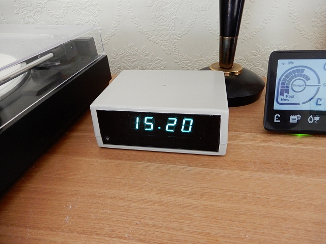
Vacuum Fluorescent Displays are available on eBay for a few UKP so it's really just a case of finding one that looks suitable. I wanted one with large digits so I used the one shown in the photos even though it only had a decimal point rather than a colon to separate the hours and minutes.The manufacturer's part number is usually written on the back and, if you're lucky, you may find a datasheet for it. Otherwise, it's a case of checking it out carefully and identifying which pin does what.
 The filament pins are invariably the end pins. You can easily see the filament wires stretched across the display and note how they're anchored under tension at the ends.
For testing purposes, apply no more than 3 volts DC across the filament. If you can see the filament glowing - even in a darkened room - the voltage is too high!
The filament pins are the only pair of pins with a relatively low resistance between them - probably in the order of 15 or 20 Ohms.
The filament pins are invariably the end pins. You can easily see the filament wires stretched across the display and note how they're anchored under tension at the ends.
For testing purposes, apply no more than 3 volts DC across the filament. If you can see the filament glowing - even in a darkened room - the voltage is too high!
The filament pins are the only pair of pins with a relatively low resistance between them - probably in the order of 15 or 20 Ohms.
It should be relatively easy to locate the pins connected to the grids. As with my display, there is often more than one pin connected to each grid as some of the pins are used to anchor the grid mechanically as much as for anything else. Now, connect the negative of a 12 volt DC supply to the negative of the filament supply and connect the +12v to the pin connecting to one of the grids. In this photo, I used the second grid from the left.
You can now carefully also connect the +12v to other pins. Note which pins illuminate the a, b, c, d, e, f and g segments. In this photo, I held the +12v test lead across two segment pins so two segments are lit.
Once you've identified which pins correspond with the a - g segments, move the +12v from the first grid to another grid and confirm the same segment pins still illuminate the a - g segments but now on the "new" digit.
Note that 12 volts is probably enough to give the segments good brightness when testing "statically" but, once the display is multiplexed, considerably more voltage will be needed. It's easiest to derive the high voltage from the project's 5 volts supply using a small DC-DC boost module. Luckily, they usually have a good range of voltage adjustment to set the final grid & segment voltage.
Incidentally, the segments in this photo aren't as bright as they appear - the
camera seems particularly sensitive to the phosphor colour.
VFD Clock
I used a standard micro USB socket (on a little breakout board) for the 5 volts power input. I haven't included a 5 volt regulator in the circuit so using a USB socket for the power input seemed sensible to prevent a higher voltage adapter being used in error. The total current consumption from the 5 volt supply varies greatly depending on the output voltage from the DC-DC Boost converter and can range from around 150mA to 350mA or so.
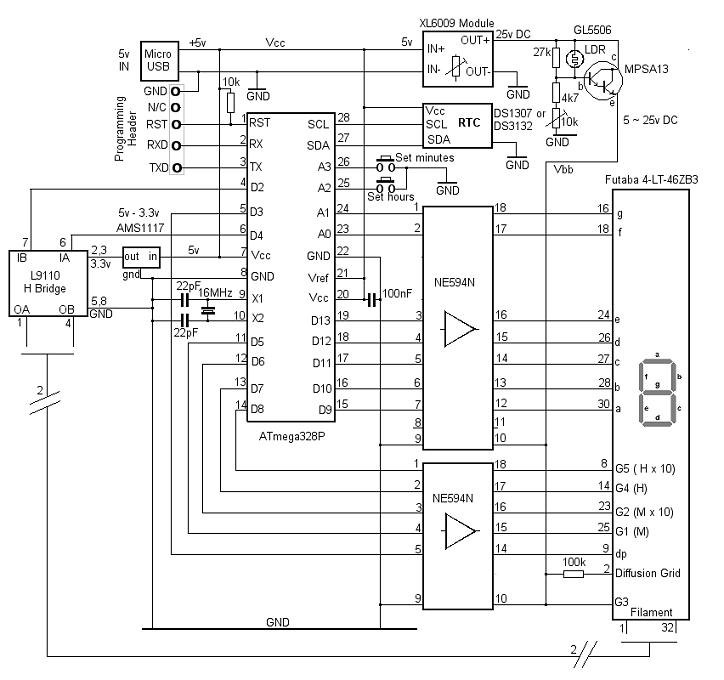
The 5 volts is taken directly to the ATmega328P, to the Real Time Clock module and to the input side of a XL6009 DC-to-DC boost converter. The converter's output is adjustable via an on-board pre-set potentiometer up to at least 30 volts. The output from the XL6009 module passes through a MPSA13 Darlington transistor to the +ve pin (Vbb) on the segment and anode driver ICs (NE594N).
The light dependent resistor (LDR) with the 27kΩ parallel resistor and 10kΩ preset with the 4k7 series resistor form a potential divider to control the MPSA13's base voltage. In full brightness, the MPSA13 is fully on and the voltage at the emitter (and the supply voltage to the display's segments and grids) is the same as the output from the XL6009. In darkness, the emitter voltage falls to around 5 volts and the display is proportionately dimmed. The total current drawn by the 25v rail in full brightness is typically less than 15mA but the current on the 5 volt side of the XL6009 is around 230mA.
The circuit also works with the slightly less expensive MT3608 DC-DC boost coverter but, as their output voltage can be unstable, I decided against using one.
I used the higher precision DS3231 clock module in place of the DS1307 RTC and I've made the PCB compatible with the pinout of popular versions of both. Both modules use the I2C interface on pins 27 and 28 of the ATmega328P and use the same Arduino RTCLib software library.
The Filament Voltage
The filament voltage is probably one of the most critical items in terms of longevity of the display so it's worth getting it right - or at least not exceeding it's maximum voltage. Bear in mind the voltage specified in a display's datasheet is probably for AC RMS so I think it's worth keeping a DC square wave voltage somewhat lower.
 I included an L9110 H-Bridge IC to supply the display filament as
it removes any doubt about the current drawn from the ATmega328P IO pins (D2 and D4).
I included an L9110 H-Bridge IC to supply the display filament as
it removes any doubt about the current drawn from the ATmega328P IO pins (D2 and D4).
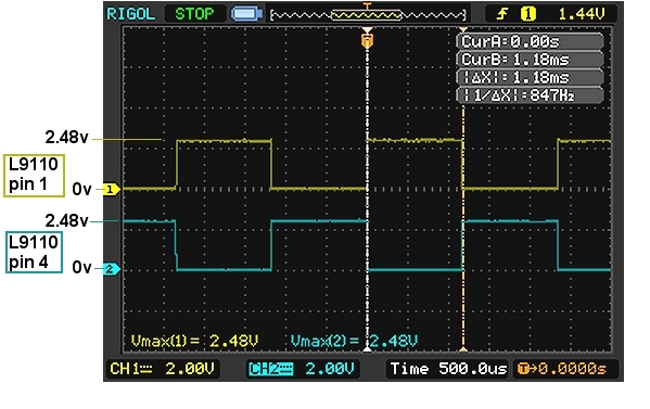
I also included a 5v to 3.3v buck regulator in the Vcc supply to the H-Bridge to ensure that the filament voltage can't exceed 3.3 volts.
In fact, with a 3.3 volts supply and 5 volts applied to the inputs, each output to ground from the H-Bridge is 2.48 volts.
Measuring the voltage across the filament can be confusing - even with the oscilloscope - as it will measure the peak-peak at around 5v but only half of that will be across the filament at any moment.
If your display is happy at 5 volts, the regulator can obviously be left out and, if your display filament uses less than about 40mA, the H-Bridge can be left out altogether.
Segment and Grid Drivers
The NE594N Vacuum fluorescent display driver enables the ATmega328P's 5v IO pins to switch the 20 ~ 25v to the display's segments and grids. The UDN6118A is an identical alternaive.
Diffusion Grid
Note that the VFD pin numbers in the circuit above are specific to the Futaba 4-LT-46ZB3. Pin 2 (Diffusion Grid) is a conductive coating on the inside of the front glass. It's purpose it to prevent electrostatic build-up on the outside of the display which can affect the evenness of the distribution of the electrons and the luminance of the display. (See Page 13 6.5 of this very useful Futaba Application Note). Some displays have that connection, some don't. I ran my display for several days without the connecion being made and I didn't notice any difference. The application note recommends it is connected to a positive supply via a resistor although it doesn't specify what value.