 This page details connecting the Honeywell HMC6352 Digital Compass to the PICAXE 18M2. I bought the compass module from
Cool Components.
This page details connecting the Honeywell HMC6352 Digital Compass to the PICAXE 18M2. I bought the compass module from
Cool Components.
I2C
Although the datasheet for the HMC6352 states the maximum supply voltage is 5.2v, the specifications and an example circuit show 3v being typical. As I wanted to gain some experience connecting different voltage devices together, I opted to supply it with 3.3 volts. The module uses the I2C protocol to communicate with the Microcontroller so I'd be able to get some experience with that as well.My first attempt at connecting the module to the Picaxe didn't go too well because I'd forgotten to take into account that I2C outputs are 'open collector' rather than being at simple CMOS logic level. The 'posh' level-converter chip that I'd bought was useless with the I2C bus. The guys on the Picaxe forum soon set me on the right road... two roads, actually!
Open Collectors
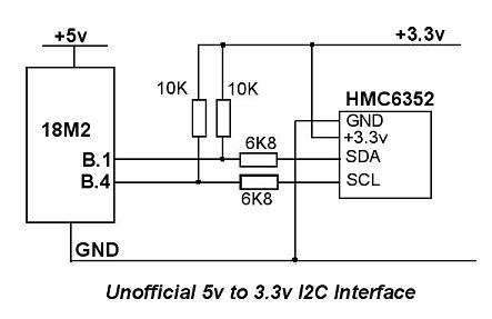
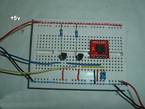
The first way to connect two I2C devices of different voltages relies on their open collector outputs. Provided the necessary pull-up resistors are connected to the lower voltage supply (3.3v in this case), the outputs - even from the device supplied with 5 volts - can only ever be 3.3 volts. And, provided the 5v device (the Picaxe) will accept a high logic level of only 3v from the compass module, the I2C connection should work.There are a couple of assumptions there and there's another assumption - or caveat - as well. In this particular scenario, the Picaxe's versatility could be its downfall - or rather the compass module's downfall. Provided (there's that word again!), provided the Picaxe's I2C pins are configured correctly and do not at any time assume a "normal" high logic level 5v, all will be well. But give a normal 'high' command and the output is no longer open collector and the full 5 volts will be applied to the compass module.
In this particular case, it's still within the compass module's maximum voltage limit but, as a general rule, it's best to remember this caveat when using this technique to connect different voltage I2C devices together. And even here, the compass module may not take kindly to having its inputs at a higher voltage than its supply.
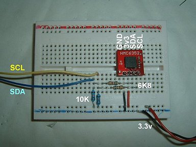
Note that the 10K pullup resistors are connected to the lower (3.3v) supply. The two 6k8 resistors are there to try to prevent any collateral damage if the outputs from the Picaxe decide to go to a normal logic high. The resistors should restrict the compass module's input current to less than 1mA.
 | 
|
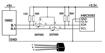
Bi-directional level shifter for I2C-bus
The I2C-bus was introduced in 1980 by Philips Semiconductors and, in Application Note AN97055 they detail a simple bi-directional level-shifter for the I2C bus using two MOSFETS.There's a thorough, in depth, discussion about the technique in the application note so there's no point repeating it here. Suffice it to say, it offers a great deal more protection to the lower-voltage device if the Picaxe decides to get off the I2C bus.
 |  |
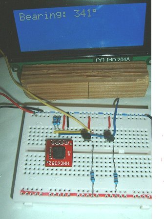
In its default power-up mode, retrieving the magnetic bearing from the compass module is a simple 2-step process:
Write the command "A" ($41) to the module and then read the next two bytes. There is a 6ms delay between writing the "A" command and being able to retrieve the value - hence the 'pause 10' command between the two operations in the program. The retrieved bytes represent the magnetic bearing, high byte first. Reading the two bytes into Picaxe variables b1 and b0 means the word variable w0 contains the full value to one decimal place. Dividing w0 by 10 produces the bearing to 1-degree resolution.
; HMC6352 compass module

  Symbol Calibrate = pinC.0				;Calibrate switch

init:

  hsersetup B9600_4, %10000 				;Use LCD Pin 1, no hserin

  hserout 0, (13) : pause 100           		;Initialize LCD
  hserout 0, (13) : pause 100
  hserout 0, (13) : pause 100
  pause 500
  hserout 0, ("ac1", 13)  				;Clear display
  pause 50
  hserout 0, ("acc", 13)                  		;Hide cursor

  hi2csetup i2cmaster, $42, i2cslow, i2cbyte

main:
  if Calibrate = 0 then 				;Calibration mode
    hi2cout ("C")
    do
    loop until Calibrate <> 0
    hi2cout ("E")					;End calibration
  endif


  hi2cout ("A")						;Normal Aquire data
  pause 10

  hi2cin (b1, b0)

  hserout 0, ("ac80", 13)				;Position LCD cursor
  hserout 0, ("adBearing: ", 13)
  w0 = w0 / 10
  hserout 0, ("ad", #w0, $df, "  ", 13)

  pause 100
  goto main