 |
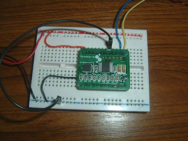
This module is supposed to offer both UART and I2C outputs (although not at the same time). It also has a choice
of either 5v or 3.3v power supply so, it should be easy to use. The choice between uart and I2C is selected by tying pin 5 to either +5 or 0v respectively. Unfortunately, I've had no success at all with the uart and the results returned from the I2C interface are a bit confusing (at least to me).
|
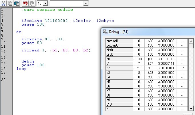
The device's address is $60 (% 0110 0000). Four versions of the chip are available with different I2C addresses. $60, $64, $68 and $6C (% 0110 xx00).
Writing a '1' to the module's register (address 0) triggers the device into sending 5 bytes of data from consecutive register addresses:
The register contents, x-axis MSB, x-axis LSB, y-axis MSB and y-axis LSB. As we're not interested in the register contents [*], the I2C Read operation can begin at address 1.
According to Sure datasheet, the module has a 12-bit resolution, the top 4 bits of each MSB being zeros. Unless I'm reading the module incorrectly, it didn't work like that. The MSB of each axis was either 00000111 or 00001000 ie either 7 or 8.
The LSB for each axis produced an output between 0 and 255 - twice for each revolution. The MSB was 7 for half of the rotation and 8 for the other 180 degrees. Therefore, it wasn't possible to get a simple 16-bit value from the Picaxe word variables (b1:b0 and b3:b2). The relationship between the x and y axes is 90 degrees (obviously!) but some decent maths between the two axes may yield better resolution than the apparent 9-bit.
[*] It may be that the register contents are more relevant that it apears. More work on this module is required, but disappointing so far - not helped by comparatively poor documentation!