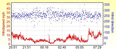
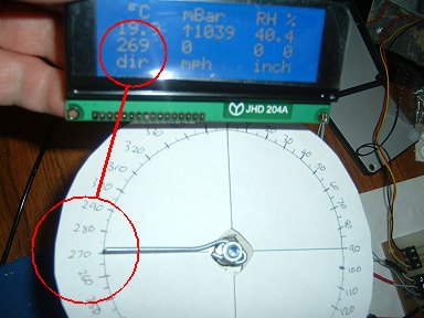
 Example plot from the software running on the PC. The wind direction is plotted as a
series of dots.
Example plot from the software running on the PC. The wind direction is plotted as a
series of dots.
The Wind Direction - Mechanical Details
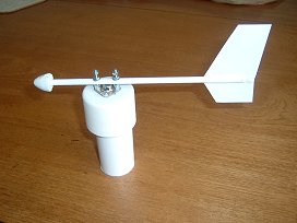
The wind-vane prior to making the electrical |  |
The wind direction sensor has proved to be the most troublesome! It's very erratic due, I suspect, to its location. The grub screw holding the 'hub' to the central shaft has worked loose twice. I've now filed a flat on the shaft to see if this helps.
[June 2018]
The 'protective cap' is a suitably-sized bottle top attached with weatherproof sealant. After over 7 years continuous exposure
to the weather, the cap had virtually eroded away. Removed the old sealant and what little was left of the old cap and renewed with a new cap.
[October 2020]
The rotating hub (the cap from a spray paint can) is showing a lot of wear. One side is effectively always facing the wind so I guess this is
inevitable and will probably need replacing after this winter.
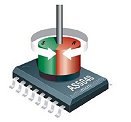 |
For the wind direction sensor, the aluminium flag in the windspeed sensor is replaced with a magnet and, instead of the
slotted opto-switch, a special-purpose IC manufactured by AustriaMicroSystems is positioned directly under the magnet. Section 15 of the IC Datasheet suggests specifications for suitable magnets. |
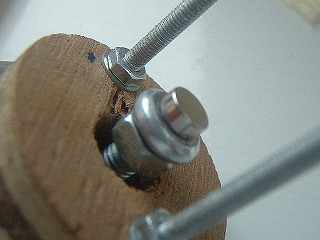 |
This photo shows the magnet superglued to the head of the central 5mm screw. I filed the screw-head flat and used an
engineer's square
to check that it was precisely at right angles to the length of the screw. Alignment of the magnet to the top surface of the
IC is critical. The datasheet specifies that it must be within 0.25mm of the centre of the IC. The magnet must be absolutely central on the head of the screw, parallel to the face of the chip and spaced between 0.5mm and 1.5mm from it. Once everything is accurately aligned, all the nuts are treated with a dab of Locktite Thread Sealer. Several suppliers of suitable magnets are listed on the AustriaMicroSystems website but, by clicking "Order Sample" on this page, you can order a couple of free samples. Suitable magnets are available from First4Magnets.com. They slightly thinner and less powerful so the alignment needs to absolutely spot on to ensure accuracy. |
The Wind Direction Electronics
There are a variety of different schemes for sensing the direction of the wind. They mostly consist of either an array of 8 reed switches arranged at 45 degree intervals with a rotating magnet or a 360-degree (continuous rotation) potentiometer.Both methods have their advantages and disadvantages. The major advantage is that they're both simple to implement. The disadvantage is that they're subject to wear and tear - especially a potentiometer.
An alternative to using reed switches would be to use Hall-effect sensors to solve the mechanical wear but they are still limited to their 8 distinct positions... Actually, by careful placement of the magnet, both reed switches and Hall effect sensors can be persuaded to provide a "pseudo" 16-position output (22.5 degree resolution) by allowing adjacent switches to be operated at the same time.
Ideally, I wanted to try something different and eventually decided on an AS5040 rotary magnetic encoder IC. Although it's a Surface Mount Device (which I try to avoid), it has several advantages which make its use appealing!
It has several different output formats, two of which are most suited to our purpose. The best accuracy is obtained through a digital (SSI) interface. However, as the signals would have to travel at least a couple of metres between the elevated sensor and the outdoor ground unit, this would quite likely have required a separate Picaxe on the masthead with a serial link to the ground unit - unnecessarily adding to the complexity.
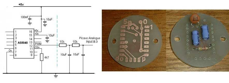
The AS5040 has a Pulse Width Modulation output providing pulse widths between 1µs at 0 ° and 1024 µs at 359.6° Unfortunately an 18M2 Picaxe would be struggling to resolve the shortest of the AS5040's output pulses but, by feeding the PWM output into a simple RC filter circuit, a 0-5 volt analogue signal can easily be generated up at the sensor unit providing the ground-based Picaxe with a simple analogue input accurate to within about 5 degrees of rotation. The AS5040 datasheet suggests this method is perfectly suited to replacing potentiometers so this is the method I've chosen here.
There's a more detailed description of some tests I did with the AS5040 here.
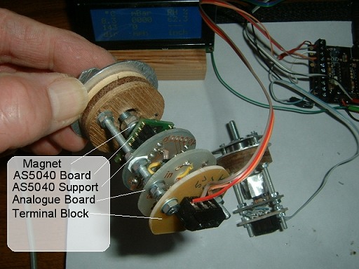 |
This photo shows the assembled wind direction sensor.
|
Checking the calibration of the wind direction sensor:
   do
      readadc10 B.3, w0    ;Read from AS5040 magnetic bearing
      pause 100
      w0 = w0 * 64 / 182   ; Convert to 0 - 360 (degrees)
      debug		   ; Display in Prog/Edit debug window
   loop
(Thanks to 'hippy' and others for guidance with
the maths.)