The Indoor Unit - Circuit Diagram
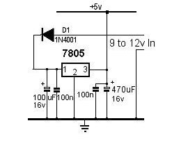 The indoor unit uses an 18M2 Picaxe and houses the pressure sensor circuit and LCD display. The 5 volt regulator circuit
is on the same PCB and is shown on the right:-
The indoor unit uses an 18M2 Picaxe and houses the pressure sensor circuit and LCD display. The 5 volt regulator circuit
is on the same PCB and is shown on the right:-
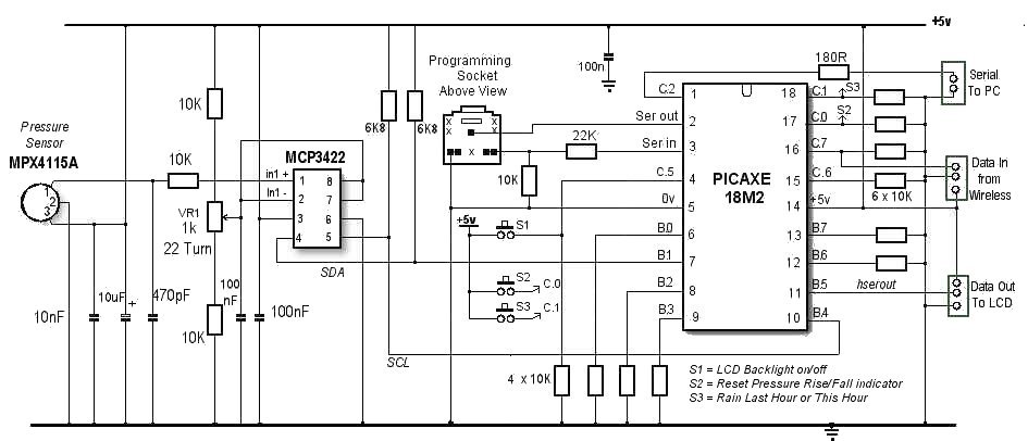
The Pressure Sensor Circuit
After a few false starts trying various pressure sensors, I settled on the easily-obtainable MPX4115A manufactured by Freescale Semiconductor. (Farnell Order code: 1457150).Although other sensors have a measuring range slightly more suited to barometric pressure measurements, most are not quite so easily obtainable here in the UK and they tend not to be available with what, for me, are easily-managed package sizes. Additionally, other sensors tend to operate at 3 volts requiring and additional voltage regulator and some voltage level-shifting circuitry to interface with a 5 volt Picaxe system.
The MPX4115A outputs an analogue voltage proportional to the pressure which, for a barometer, means between about 3.79 and 4.25 volts.
Although this is just about enough resolution to detect a 1 mBar pressure change, after some discussion on the
Picaxe Forum, I added an MCP3422 Analogue to Digital Converter.
This has the advantage that it can operate in full 16-bit mode (or higher) compared with the 10-bit mode (at best) of the native Picaxe. The MCP3422 can be connected (as in our circuit) in differential mode, with the analogue input from the MPX4115A sensor being applied to the +ve input pin and compared with a reference voltage (2.5 volts) applied to the -ve input pin from the potential divider formed by two 10K resistors and a 22 turn 1K preset potentiometer connected across the power rails. A major advantage is that this allows the output from the chip to be adjusted, thereby easily compensating for inherent errors in the MPX4115A and to provide a simple method of calibrating the sensor against a known local pressure standard (such as the data reported by a local airport).
The MPC3422 actually has two differential inputs and, as the datasheet doesn't specify what to do with unused inputs, I tied them both to the -ve input on the input we're using.
Output from the MCP3422 is an I2C interface and connects with the dedicated SDA and SCL pins on the 18M2 Picaxe - pins B.1 and B.4 respectively.
Many thanks to 'matherp' in the above forum discussion for the code which worked straight off! (And thanks also to 'westaust55' for his help with the HP03 Pressure Sensor even though, ultimately, I decided to use the MPX4115A instead).
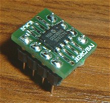 | From my point of view, the only disadvantage in using the MCP3422 is that it's a small surface mount device but I had it soldered to a beakout (or adaptor) board by my usual company. |
The Indoor Unit - The 18M2 Picaxe
In addition to the I2C interface from the MCP3422 and the usual circuit associated with the programming socket, the remainder of the 18M2 simply handles the incoming data from the 433MHz wireless receiver, displays the data on the LCD display and passes the data out on the serial connection to the PC. To avoid the indoor unit "stalling" when the PC isn't running, there's no handshaking between the indoor unit and the PC. The indoor unit sends the data and moves on. It sends the data at approximately 2-second intervals to any data lost is quickly picked up next time round.I've brought three of the spare inputs on the 18M2 out to 'pads' on the PCB to connect to normally-open push buttons on the front panel. Switch S1 (input C.5) is used to turn the LCD backlight on and off. Switch S2, (input C.0) resets the "up/down indicator" alongside the pressure value (mBar) on the LCD display. The up/down indicator is just an up or down arrow character indicating whether the pressure is rising or falling. Switch S3 (input C.1) toggles the rainfall display on the LCD between the total in the previous hour and the current running total in current hour. There's not really enough space on the LCD to display both at the same time.
Because the main program loop is predominantly serin and serout commands, which disable interrupts, I found there was no noticable benefit in using interrupts with the switches. In order to keep the software in the 18M2 as simple as possible, a push button has to be held for about 1 second to take effect. I'm not very happy with the way the switches react so this may still be "work in progress".