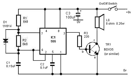
Circuit Diagram of the Alarm
|
|
We'll be referring to the circuit diagram and the table of components on subsequent pages so it may be worth printing this page.
Resistors
Resistors are simple electronic components which impede, or resist the flow of electrical current. The degree to which they impede the flow is determined by their resistance value, measured in Ohms - the greater the value, the greater the resistance and the less electrical current that flows. They're available in a vast range of values from less than 1 Ohm to many millions of Ohms. R1 and R2, in our circuit, are both 6,800 Ohms or 6.8kOhms - more usually written as 6k8. R3, towards the right hand side of the circuit, has a much lower resistance of just 220 Ohms.
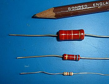
Different wattage resistors (pencil for size comparison) |
In common with many components connected across an electrical supply, they dissipate energy - they
get hot. In addition to being available in a range of resistance
values, resistors are also available in a range of power-handling capabilities. Resistors designed for use in high
power circuits will be physically large so they can dissipate large amounts of surplus energy. Those in low
power circuits, such as ours, will be physically very small.
Very often, circuit diagrams don't give the power rating of resistors so it's worth working it out very roughly. Imagine, for our circuit, a 6,800 Ohm resistor connected directly across the 9 volt supply. The current flowing through the resistor would be 9 ÷ 6800 = 0.00132 amps. The power dissipated by the resistor would be 9 x 0.00132 = 0.012 watts. So, in our circuit 0.25 watt resistors will be more than adequate.
|
OK, enough theory, let's get the project under way!