Dual Voltage, Dual Polarity Power Supply
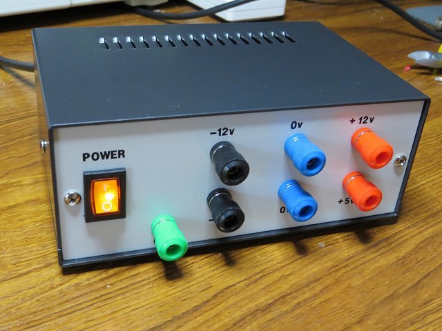
I've been working with OpAmps recently and they generally prefer a dual ±12v or ±5v power supply. Although batteries or even power "bricks" can be pressed into service to provide dual polarity supplies, I decided to do the job properly and build a reasonable-quality dual supply for future use. As one project I was working on needed both ±12v and ±5v, it seemed sensible to build both into the same bench power supply. So here is a dual-voltage, dual-polarity half-amp power supply.
Most OpAmp circuits use a few 10's of milliamps at most so a 500mA supply seemed more than enough. In pratice, with the heatsinks that I've used, the ±12v supply can manage about 750mA for a few minutes and the ±5v supply can handle close on 1A for a minute or two.
With better heatsinking and a larger transformer, all four power rails could handle 1 amp as the specified bridge rectifier is rated at 6A. Each 15v secondary winding of the transformer I've used is good for about 750mA split between the 12 volt and 5 volt outputs of each polarity - ie around 1500mA in total.
Circuit Diagram
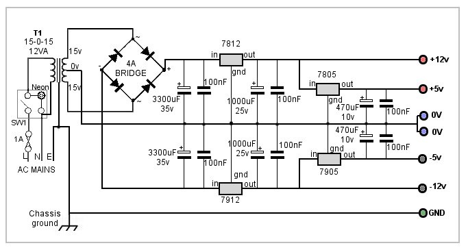
There's nothing at all special about the circuit. The only point to note is that I took the ±5v supplies off the regulated ±12v rails. Depending on the regulation of the transformer and the load current, there can be something like ±25 volts DC at the output of the bridge rectifier which I considered a bit too much for the 5 volt regulators to dissipate.
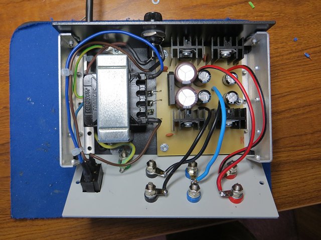
Although the incoming mains earth is connected to the enclosure metalwork, the common 0v rail from the centre-tap of the transformer secondary is deliberately not connected to the enclosure. I decided to leave the 0v connection "floating" to avoid any possible mains/grounding conflicts but I brought the chassis/mains ground out to a binding post so it can be connected to 0v if preferred.
Safety Considerations
This project uses potentially lethal mains voltages. Do NOT skimp on safety arrangements such as earthing (grounding), fuses, ventilation and preventing access to live parts through ventilation slots.
Use a good quality screw-in type panel fuse and ensure that the design is such that, when removing the fuse holder, it is well clear of live internal contacts before there is sufficient clearance to be able to touch the fuse (or the holder's metal parts) with your fingers.
The mains earth (ground) lead is connected to the enclosure through the transformer mounting bolt.
Note that any parts of the enclosure that are attached separately (such as the front & rear panels and the top attached with self-tapping screws, for example) should have their own earth wire back to the same transformer mounting bolt. Do not rely on the self-tapping screws for earth continuity. Try to leave the incoming earth conductor longer than the live and neutral conductors so that, if the cable does get forcibly pulled, the earth will be the last conductor to break.
All exposed mains-voltage connections - to the illuminated switch, the fuseholder and the transformer - must be insulated with heat-shrink sleeving and/or access prevented with insulating covers. It should not be possible to make contact with any high voltage connections - even with the top cover removed - without a determined and conscious effort!
The mains cable entering through the rear panel must be protected from chafing with a rubber grommet and the cable must be clamped against moving inside the enclosure to prevent the connections being pulled or twisted and to prevent the grommet being pulled from its hole.
Despite what commercial products may do, do not use the printed circuit board for any mains voltage part of the circuit.
The Printed Circuit Board
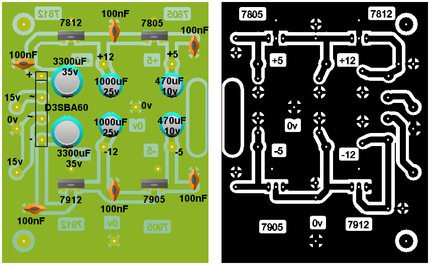
Download PCB artwork in Circuit Wizard Format.
Download/view Actual size PCB artwork in PDF Format.
Construction
| 15v+15v 12VA Transformer | Rapid Electronics |
| 150x100x60mm aluminium enclosure | eBay (Discount Devices Electronics Shop) |
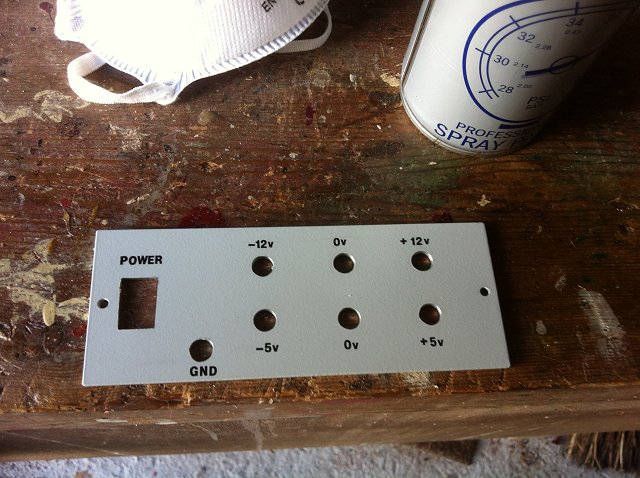
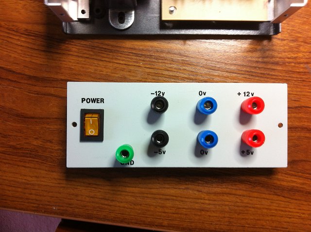
I used Letraset for the panel labels and sprayed with half a dozen coats of clear cellulose laquer to help stop the letters rubbing off.
The rectangular hole for the power switch was made by chain-drilling and filing.
I found the multi-coloured binding posts on eBay in packs of one each of 5 colours. I'm not overly impressed: They don't have a "keyway" or "spigot" to stop them rotating in the hole when the outside knurled "thumb screw" is tightened and the thread on the thumb screw is loose and quite short. I wouldn't recommend them for frequently wrapping test leads around but they're fine for use with 4mm banana plugs.
Note that the INPUT connection on the negative regulators is not isolated from their metal tabs so they should be insulated from their heatsinks with TO220 mica or rubber insulating kits. This is especially important if the heatsinks have a locating pin which protrudes through the PCB and makes contact with the (0v) ground plane.
Although the mounting-hole locations on the PCB are isolated from 0v, I mounted it on insulating bushes as an added precaution.
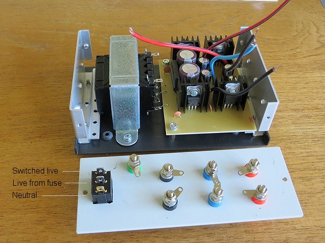
The illuminated power switch was also from eBay. You may need to check out the connections with an ohmmeter but, generally, the neutral connection for the neon is a different colour (brass rather than tinned) or is spaced further apart than the other two connections. If the neon it lit all the time, you need to swap over the incoming live from the fuse and the switched live. To state the obvious, make sure you order one for AC mains use. Others designed for 12v car use have an LED instead of the neon.
Testing
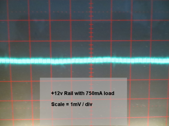
Ripple and noise figures are notoriously difficult to measure (See EEVblog's video) but ripple on all the outputs is less than 2mV p-p when feeding a 1.0A load - ie twice the designed load.My old analogue oscilloscope is better than the Digital Storage Oscilloscope for this job: It has 1mV/div vertical scale (5mV/div x 5 magnification) whereas the best the DSO can manage is 20mV/div. There's a small amount of high frequency common mode noise on the signal, which is present even when the power supply is switched off, so it's probably coming from the PCs or monitors.
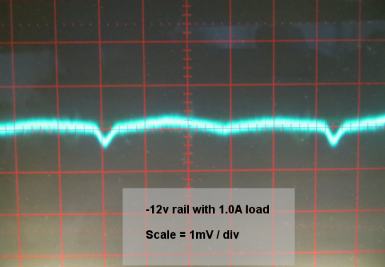
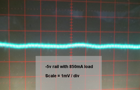
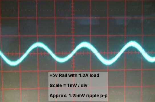
Ripple performance of the positive and negative outputs is very similar so, for example, on both 12 volt outputs, the ripple is negligible at 750mA but rises to about 0.5mV p-p with a 1 amp load. Similarly, the ripple on both 5 volt outputs is negligible at 850mA load but rises to about 1.25mV p-p with a 1.2A load.