Headphones Out to Line In
My old one had a "massive" 64MB so it was time for an update!
As a bonus, I was given an unwanted iPod Docking Station by my brother. Although my new player wouldn't dock with it, luckily it had a 'Line In' socket so I should be able to plug my MP3 player's headphone socket into it with a simple lead with a 3.5mm plug at each end. Unfortunately, when I tried it, the audio was very low level and very distorted. No amount of adjusting of either device's volume control helped.
 |
Headphone sockets on portable equipment are designed to feed into a load of around 32 ohms whereas Line In sockets are much
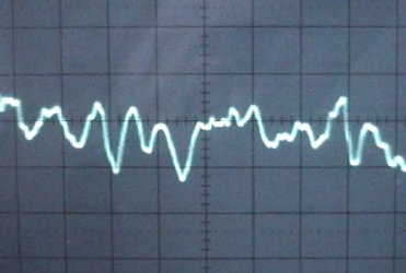
higher impedance than that. The typical voltage levels could also differ a lot. I hooked up the MP3 player's headphone socket to the oscilloscope with a 100 ohm resistor as a load. Remember that headphones are 32 ohms impedance so it was best to err on the high side for a substitute resistor. The trace showed only about 100 mV peak to peak when the volume on the player was set to a "normal" level, so the voltage didn't seem excessiveky high to feed Line In. Feeding a high impedance input from a low impedance source wouldn't 'bother' the input so the problem with using a "plain" lead with a 3.5mm plug on each end was simply that the player wanted to "see" a lower impedance load than the Line In was providing. The audio frequency response is tailored around the load of 32 ohm headphones. |
|
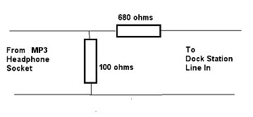
I decided to add a series resistor to increase the impedance a bit. Values aren't at all critical - but don't go too
low with the 100 ohm parallel resistor. I used a piece of veroboard initially so I could experiment with the resistor values.
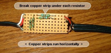
There are two of each value resistor because it's stereo. Don't be misled by the apparent mis-match of the two red cores in the picture on the left. I just used two odd bits of cable from my scrap box which already had 3.5mm plugs on one end. One piece of cable had the red core going to the plug's tip, the other piece had the white core. Plug-tip to plug-tip through the 680 ohm resistor and plug-ring to plug-ring through the second 680 ohm resistor is all that matters.The plug-barrel (the ground connection) just goes straight through. |
 | 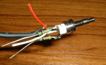 |
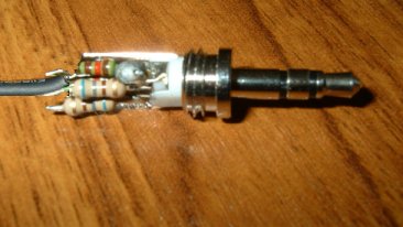 |
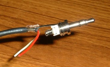
With the veroboard wrapped in black tape, it could hardly be seen so the lead could be used as it was but I eventually managed to
fit tiny 1/8 watt resistors into a 3.5mm plug. It wasn't easy - I wrecked two plugs and a handful of the resistors before I found
the right knack to getting the 'package' small enough to get the plug top on. A simpler alternative would have been to fit the 100 ohm parallel resistors in one plug and the 680 ohm series resistors in the other plug. However, I wanted to use a lead with a moulded plug already on one end! Remember that the lead only works properly one way round so it's better to mark one end so you know which end is which! |