Other Vertical Adjustments
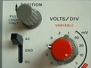
Take another look at the picture of the Y-Amplifier. It's important to have the switch
marked AC - GND - DC in the correct position to correspond with the voltage being
measured.
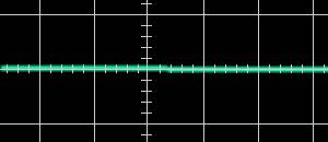
By initially setting the switch to GND, the vertical position control can be used to set the resulting straight line trace exactly on the grid's centerline (as shown in the bottom picture) so allowing very accurate measurements of the subsequent waveforms above and below the line.
Setting the switch to AC or DC to correspond with the input voltage will ensure that the vertical displacement of the display on the screen is correct.
On this particular oscilloscope, there is a continuously variable adjustment of gain by turning the red knob, but, in this case, the accurate volts/div or mV/div will no longer apply. It is usually better to leave the setting in the 'Calibrated' position.