USB Power Adapter
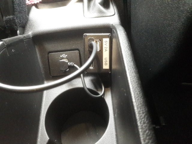
The USB sockets for the car's "entertainment system" gives more predictable power; they power up as soon as a door is opened to get in and power down about ten seconds after a door is closed after getting out. Not perfect as there are rare occasions when I stop the car and don't get out but it was good enough - except for one issue:
When the dashcam is powered from the USB socket, the dashcam insists on entering PC-Data transfer mode rather than dashcam power/charging mode. I made a temporary fix by cutting open the USB cable and breaking (and insulating) the two data wires (data+ and data-). Although this works, it has a niggling annoyance that I have to use a "bespoke" cable. Also, of course, using the USB socket to permanently power the dashcam means it is no longer available for its intended purpose(s) without using a USB hub.
This simple "mini-project" addresses those issues and I think provides a neat solution.
The Circuit
It's hardly worth showing the circuit as it's so straightforward but here it is anyway.....
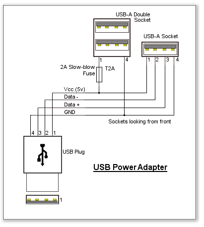
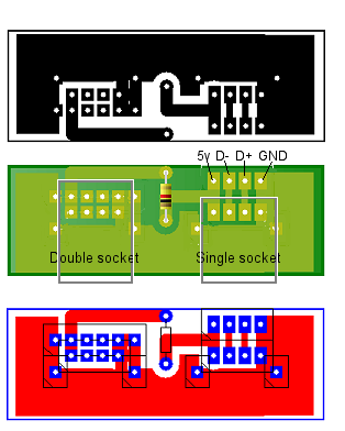
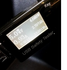 As can be seen here, the dashcam takes almost 1.0A while its screen is on. As it
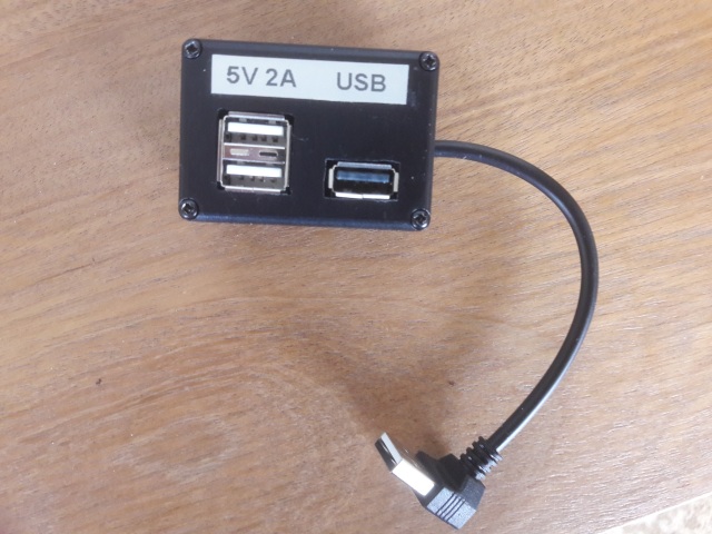
seemed sensible to fit a double USB socket (for a rear-facing camera in the future), I decided to fit a 2.0A fuse.
As can be seen here, the dashcam takes almost 1.0A while its screen is on. As it
seemed sensible to fit a double USB socket (for a rear-facing camera in the future), I decided to fit a 2.0A fuse.
I used a normal PCB-mounted slow-blow non-resettable fuse rather than a polyfuse as I felt its operation was more predictable for this use.
A polyfuse typically has a nominal resistance of around 0.4 ohms. Given the 1.0A drawn by the camera, I considered
the 0.4v drop across a polyfuse to be excessive - especially considering the fairly long (4m) USB cable feeding the camera which will
have a significant voltage drop of its own.
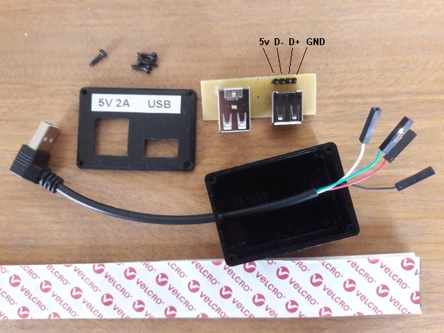
I've used a right-angle USB plug to connect to the car's socket because it looks neater. When making up that short cable (by cutting off whatever is on the other end), don't assume that the wires will follow the expected colour-code! After preparing the cable as shown in the photo below, determine which wire is which using an ohm-meter. Provided the wires are suitably insulated, insert the plug into a USB socket on a PC (for example) and double-check the +5v and Ground lines.
Although the cable I used had the correct coloured wires, not a single one was the colour you'd expect.