Building the case
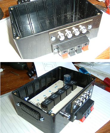
As this project is to remotely switch video cameras, this switchbox is going to be tucked away in the corner of my garage so there was no point wasting money on a fancy-looking case.These photographs simply show a couple of stages during the fitting of the various sockets. At each stage, the PCB was tested to check that the sockets would not prevent the board from being fitted.
The red and black lever connectors are for the 12v supply to the box and for the 12v supplies to the four cameras. The group of four white phono sockets are for the video in from the cameras and the scart socket and the final phono socket are for the selected video output.