Car Battery Voltage Monitor
There are many devices which are designed to plug into a car's auxiliary socket (formerly known as the cigarette lighter socket) which, ideally, depend upon the voltage turning off with the ignition. One such device, which I've recently fitted to my own car, is a dashcam. Luckily, the power to my car's auxiliary socket is switched with the ignition but there are a lot of cars in which the power isn't switched with the ignition.
I've spotted one or two dashcams which can automatically sense if the engine is running but they tend to be very top of the range devices costing £150++. For the rest of us, it's inconvenient to keep plugging in and un-plugging the dashcam's power lead at the start and end of each journey (or fitting some sort of switch) and, in any event, is likely to be forgotten just when it's needed!
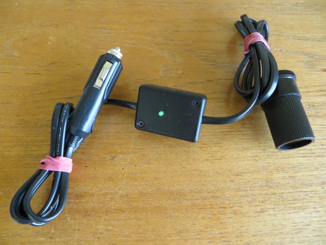
This project is designed to monitor the battery's voltage to determine whether the engine is running or not. It plugs into the auxiliary socket at the "front end" and has it's own switched auxiliary socket at the "rear end". I've only been able to find one commercially-available product which does the same and, in my opinion, it seems a bit expensive. Depending on what you already have in your spares box, this project should cost about a third of its commercial counterpart.
Circuit Diagram
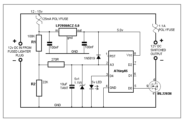
A potential divider consisting of a 100K resistor and a 22K resistor (R1 and R2) is connected across the incoming 12 volt supply from the auxiliary socket. The fairly high values are chosen deliberately so as to draw very little current from the battery. The input voltage can be up to 28 volts before the voltage at the junction exceeds the microcontroller's 5 volt limit. The 270R resistor at the potential divider junction and the 10uF tantalum capacitor smooth any ripple noise from the alternator.
Although the car battery should absorb most alternator-generated voltage spikes, high frequency noise from the ignition system could "by-pass" the battey and be induced directly into this circuit's input through the vehicle's wiring. The 5v1 zener diode and the 1N5819 schottky diode are to help protect the ATtiny85 analogue input pin A3 from such voltage spikes.
The ATtiny85 simply "measures" the voltage and outputs 5 volts on pin D0 to the gate of the IRL2203N MOSFET whenever the voltage is above a certain threshold - set in the software at 13.75 volts. The output remains high until the voltage falls below 13.5 volts for longer than 5 seconds.
When the output is off (and the MOSFET is also off), the ATtiny85 enters sleep mode, waking up at 2-second intervals to check the battery voltage. If it's above 13.75 volts, it stays awake and turns on the MOSFET again.
When asleep, the circuit takes about 200µA thanks to the very low quiescent current taken by the LP2950-5.0 voltage regulator which supplies 5 volts to the circuit. A 5 volt LED is connected to a spare output on the ATtiny85 which flashes every 2 seconds while the circuit is asleep and illuminates fully when the MOSFET is switched on and power is supplied to the outgoing auxiliary socket.
Although it's not really relevant to the operation, the software will "double flash" the LED every two seconds if the battery voltage falls below about 12.4 volts as an indication that it may be time to consider getting a new battery.
As the project could be left plugged in and unattended for very long periods, I've been somewhat over-cautious with the fuses. In addition to the fuse built into the auxiliary plug, the circuit board has two resettable poly-fuses. A 125mA fuse protects the low current electronics and a 1.1A fuse protects the power circuit through the MOSFET and auxiliary output socket.
Although the MOSFET is capable of handling more current that the 1.1A polyfuse allows, for this circuit's intended use and considering it's enclosed in a very small unventilated plastic box, I decided to limit the current to well below the MOSFET's rating.