October 2014
Construction
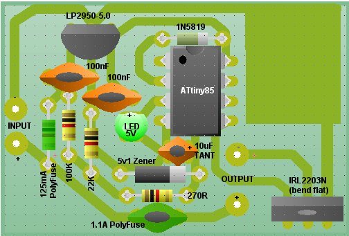
Printed Circuit Board
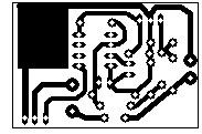
These photos show, on the left, an enlarged layout of the PCB and, on the right, the actual-size artwork.
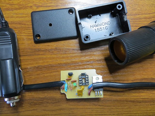
This photo shows the PCB almost completed. It's just missing the 5.1v zener diode and the ATtiny85.
Some Components
| Fused auxiliary socket plug | CPC |
| Auxiliary lighter socket | CPC |
| LP2950ACZ-5.0 LDO 5 volt regulator | CPC |
| Hammond Enclosure 50x35x17mm (Maplin code: N78BQ) | Maplin |
| ATtiny85 Microcontroller | eBay |
| IRL2203N MOSFET | eBay |
Programming the ATtiny85
The ATtiny85 is programmed using the Arduino environment with either an Arduino Uno or a dedicated programmer.It's necessary to define the ATtiny85 core so the Arduino IDE knows about its pins. Be aware there are a couple of different libraries for the ATtiny85 that treat the ATting85's internal registers differently.
The library I used is arduino-tiny. The 'README' included in the downloaded zip package contains full instructions for installing it into the Arduino IDE.
There are dozens of websites detailing how to use the Arduino Uno as a programmer - particularly for the ATtiny85 - so I won't repeat them in detail here.
In brief, the steps are:
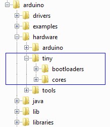
- Download the arduino-tiny library (arduino-tiny) and, with the
Arduino IDE closed, extract the files
to the main Arduino hardware folder. Something like:
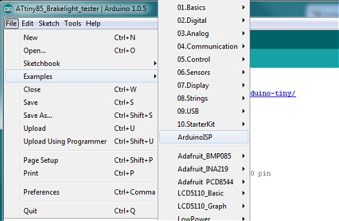
- Open the Arduino IDE and open ArduinoISP from the Examples folder. Make sure the Arduino Uno is
selected in Tools | Boards and upload the ArduinoISP sketch to the Uno in the usual way:
- Power down the Uno and connect it to the ATtiny85 as follows:
Arduino - ATtiny85 (Uno pin designations) (actual IC pin numbers) 5v - Pin 8 GND - Pin 4 D13 - Pin 7 (SCK) D12 - Pin 6 (MISO) D11 - Pin 5 (MOSI) D10 - Pin 1 (Reset) - When the Arduino Uno is acting as a programmer, it's necessary to disable its auto-reset circuit. To do this,
connect a 10uF capacitor between RESET and GND on the Arduino Uno board (Capacitor negative to GND). The capacitor 'absorbs' the auto-reset pulse from the USB/serial and prevents the Uno's ATmega328 seeing it.
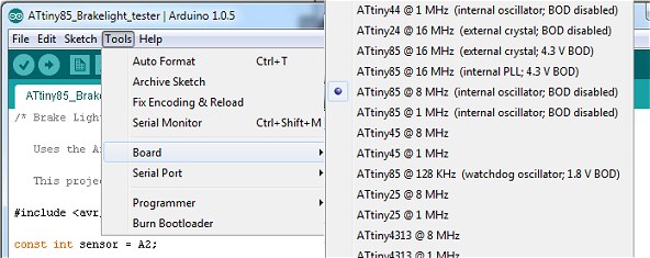
- From the Arduino Tools | Board menu, select the ATtiny85 chip: ATtiny85 @ 8 MHz (internal oscillator; BOD disabled):
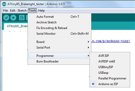
- From the Arduino Tools menu, select Programmer | Arduino as ISP.
- Power up the Arduino Uno (with the USB cable), ensure the correct COM port is still selected and, from the Tools
menu, select Burn Bootloader. This doesn't actually burn a bootloader in the ATtiny85 but it does set the internal
fuses to match the board type we selected in step 5.
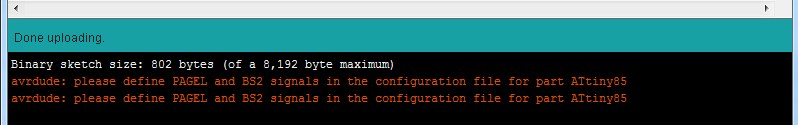
- Finally, load the Car Battery Monitor Sketch into the Arduino IDE and hit Upload in the usual way. You
will see the errors shown below. They only apply if you're using an external parallel programmer so it's safe to
ignore them. The ATtiny85 should now be successfully programmed with the Car Battery Monitor sketch.
The Arduino Sketch
/* Car battery voltage monitor - vwlowen.co.uk/arduino/car-voltage-monitor */
/* Uses ATtiny 85 with arduino-tiny core: https://code.google.com/p/arduino-tiny/  */

#include <avr/sleep.h>
#include <avr/wdt.h>

#ifndef cbi
#define cbi(sfr, bit) (_SFR_BYTE(sfr) &= ~_BV(bit))
#endif
#ifndef sbi
#define sbi(sfr, bit) (_SFR_BYTE(sfr) |= _BV(bit))
#endif

const float Vref = 5.00;              // Actual voltage and resistor values can be set here.
const float R1 =  99900.0;            // R1 is nominally 100000.0
const float R2 =  21850.0;            // R2 is nominally 22000.0

const float resDiv = (R2/(R1 + R2));  // Resistor divider factor applied to measured voltage.

const float vLow = 13.50;             // Set low voltage threshold (engine off).
const float vHigh = 13.75;            // Set high voltage threshold (engine running).

int LEDpin = 4;                       // LED flashes at power-down. Full on at power up.
int MOSFETpin = 0;                    // MOSFET power switch gate signal

int BATTpin = A3;                     // Analogue input from the 100K/22K divider.

int tim = 10;                         // Delay between low voltage checks

float getVolts() {                    // Function returns the actual battery volts.
  int raw = analogRead(BATTpin);
  float volts = (raw / 1024.0) * Vref;
  volts = (volts / resDiv);
  return volts;
}

void setup() {
  pinMode(LEDpin, OUTPUT);              // Set LED and MOSFET I/O as outputs.
  digitalWrite(LEDpin, LOW);

  pinMode(MOSFETpin, OUTPUT);
  digitalWrite(MOSFETpin, LOW);

  for (int i=0; i<4; i++) {
    digitalWrite(LEDpin, HIGH);          // Blink LED a few times to show some activity.
    delay(50);
    digitalWrite(LEDpin, LOW);
    delay(50);
  }
  setup_watchdog(7);                    // approximately 2 seconds sleep
}

void loop() {

  if (getVolts() <= vLow) {             // If battery voltage is low,
    delay(tim);                         // delay and check again, but only the
    if (getVolts() <= vLow) {           // first time around.
      tim = 10;
      digitalWrite(MOSFETpin, LOW);     // If still low, turn off MOSFET.
    }
  }

  if (getVolts() >= vHigh) {            // If battery voltage is high,
    digitalWrite(MOSFETpin, HIGH);      // turn on MOSFET and LED.
    digitalWrite(LEDpin, HIGH);
    tim = 5000;                         // Reset low-volts delay timer so it
  }                                     // will do the delayed double-check next time.

  if (tim == 10 ) system_sleep();       // If confirmed battery low, enter sleep mode.

}

// Put system into the sleep state
void system_sleep() {
  cbi(ADCSRA,ADEN);                    // switch ADC OFF to save power

  set_sleep_mode(SLEEP_MODE_PWR_DOWN); // sleep mode is set here
  sleep_enable();
  sleep_mode();                        // System sleeps here

  sleep_disable();                     // System continues execution here when watchdog times out
  sbi(ADCSRA,ADEN);                    // switch ADC back ON

  digitalWrite(LEDpin, HIGH);          // Blink LED to show some activity.
  delay(50);
  digitalWrite(LEDpin, LOW);
  if (getVolts() < 12.4) {
    delay(50);
    digitalWrite(LEDpin, HIGH);        // Blink again to show low battery.
    delay(50);
    digitalWrite(LEDpin, LOW);
  }
}

// 0=16ms, 1=32ms,2=64ms,3=128ms,4=250ms,5=500ms
// 6=1 sec,7=2 sec, 8=4 sec, 9= 8sec
void setup_watchdog(int ii) {          // set the required register bits to
                                       // set up the watcdog timer.
  byte bb;
  if (ii > 9 ) ii=9;
  bb = ii & 7;
  if (ii > 7) bb |= (1<<5);
  bb |= (1<<WDCE);

  MCUSR &= ~(1<<WDRF);
  WDTCR |= (1<<WDCE) | (1<<WDE);
  WDTCR = bb;
  WDTCR |= _BV(WDIE);
}

// Watchdog Interrupt Service / is executed when watchdog times out
ISR(WDT_vect) {
 // Include this routine even if it doesn't do anything.
}