Measuring Current with the Arduino
Although there are dedicated sensors to measure current - such as the Allegro Microsystems ACS712 (as used in my Power Supply Project), this article describes the more "traditional" method using a low value shunt resistor. Using a shunt provides a lot more flexibility in the current range that's available, rather than being "stuck" with the 5A or 30A ranges of the dedicated Hall Effect sensors.
Converting current into voltage
The Arduino's analogue input pins measure voltage (generally between 0 and 5 volts) so how do we convert current into volts?Thanks to Ohm's Law, there's a very simple linear relationship between the current flowing through a circuit and the voltage applied to the circuit.
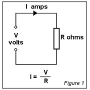 Ohm's Law states that the current flowing through a conductor between two points is
proportional to the volage difference across those points. The 'constant of proportionality' is known as the resistance and
is measured in Ohms.
Ohm's Law states that the current flowing through a conductor between two points is
proportional to the volage difference across those points. The 'constant of proportionality' is known as the resistance and
is measured in Ohms.
For example, if we have a known, fixed, resistance of 2 Ohms and we apply 6 volts across it, then the current flowing through it must be 6 ÷ 2 = 3 amps.
Similarly, if a resistance of 10 Ohms has 2 amps flowing through it, then the volatge across the resistance has to be
2 x 10 = 20 volts.
Circuits carrying Alternating Current have added complexity because the term resistance applies only to DC circuits. All circuits, have inductance and capacitance which are dependent on the frequency of the alternating current and which, when combined with the resistance of the circuit, result in the circuit's total impedance. For this simple tutorial, we'll stick with resistance and assume a DC circuit in which inductance and capacitance have no influence over Ohm's law.
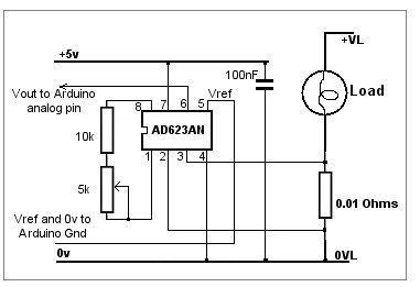
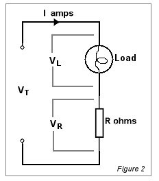 In this circuit, the resistance has been wired in series with a lamp. The lamp is the
load and we wish to know how much current it uses. It's fairly obvious that the same current (I) flows through the lamp and the resistance
so, by measuring the voltage across the resistance, we can use Ohm's Law to calculate the current.
In this circuit, the resistance has been wired in series with a lamp. The lamp is the
load and we wish to know how much current it uses. It's fairly obvious that the same current (I) flows through the lamp and the resistance
so, by measuring the voltage across the resistance, we can use Ohm's Law to calculate the current.
Let's make a couple of assumptions:
1. We want to measure current values between 0 and 5 amps maximum.
2. We'll be using an Arduino's Analog Input pin to measure the voltage across the resistance.
As the Arduino's maximum Analoge Input voltage is 5 volts, it would be convenient if we could choose a resistance value such that there is 5 volts across it when there is 5 amps passing through it..
From Ohm's Law, R = V ÷ I so 5 ÷ 5 = 1 Ohm.
Unfortunately, there are several problems with this simple approach. If we're using, for examnple, a 12 volt lamp,
it's reasonable that VT would be 12 volts. If we want 5 volts across the resistance, that only leaves 12 - 5 = 7 volts
for the lamp.
The other problem concerns 'power.' Even with a "modest" 5 amps flowing through a 1 Ohm resistance there is going to be a lot of heat generated in surplus energy. In fact, 5 amps will generate I2 x R = 25 watts' worth of heat. Whilst that sort of 'lost' energy might be acceptable when we're measuring very high currents (in the 100's of amps), it's much too high at low currents.
For both of these reasons, it's desirable to use a much lower value of resistance. The lower the resistance, the less voltage will be "lost" across it and the less heat will be generated. Unfortunately, the lower the voltage we create across it, the less voltage there is for the Arduino's Analog Input pin.
Although it's a trade-off, the over-riding factor is that the resistance we add to the circuit must have minimal effect on the circuit. It's pointless trying to measure the current in a circuit if we adversely affect that current by the very act of trying to measure it.
The Shunt
Very low Ohmic value resistors are available especially for this purpose and are generally known as shunts. The name is derived from their use with older moving coil type ammeters where a shunt is wired directly across the ammeter terminals. It's purpose is to 'shunt' most of the circuit current away from the ammeter which, itself, is designed to handle only a few milliAmps to deflect the needle fullscale.Since these resistors are generally designed for this purpose, they are sometimes rated, not just in Ohms but in millivolts at their maximum rated current.
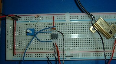
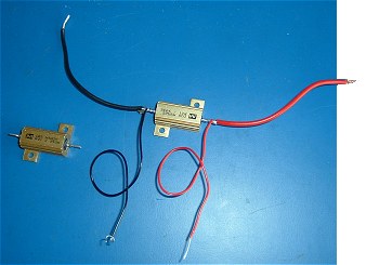 This photo shows a couple of 0.01 Ohm shunts. I've soldered a heavy lead and a
lighter lead to each end of one of them.
This photo shows a couple of 0.01 Ohm shunts. I've soldered a heavy lead and a
lighter lead to each end of one of them.
The heavy leads will carry the current of the main circuit and the lighter leads will measure the voltage across the shunt.
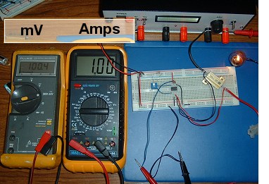
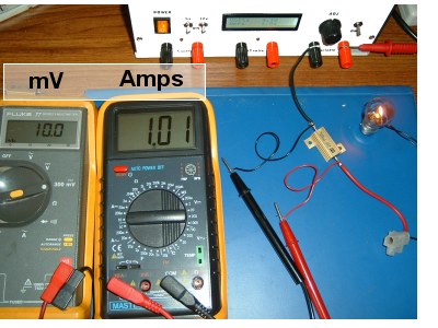 In this photo, the circuit is wired exactly as in Figure 2, above. The
right-hand meter is measuring the current through the circuit and the left-hand meter is measuring the voltage across the the
0.01 Ohm resistor. As expected, with 1 amp flowing through the lamp and the shunt, the voltage across the shunt is 10 millivolts
In this photo, the circuit is wired exactly as in Figure 2, above. The
right-hand meter is measuring the current through the circuit and the left-hand meter is measuring the voltage across the the
0.01 Ohm resistor. As expected, with 1 amp flowing through the lamp and the shunt, the voltage across the shunt is 10 millivolts
It's worth noting that it doesn't matter what other voltages we could measure between other points in the circuit. 1 amp is 1 amp whether it's flowing through the lamp or the shunt. All we need to know is that, if the current is 1 amp and the shunt is 0.01 Ohms, then it must have 10mV across it.
Or, to put it the other way: If there is 10mV across the 0.01 Ohm shunt then there must be 1 amp flowing through it.
.
The Arduino
The Arduino's Analog Input Pins work between 0 and AVref - which is normally between 0 and 5 volts.As the digital value is between 0 and 1023, the digital value is 1023/5 = 204 per volt (rounded down, as the value is an integer value).
If we relate this to the 10mV per amp from the shunt, we can see that the smallest step change in the current that we can resolve with the Arduino is 0.5 amps. (204 adc units per 1000mV = 2 units per 10mV. ie 2 units per amp or 0.5 amps per unit). This resolution may well be good enough if we're measuring 10's of amps but is no use if we're trying to measure current in the range of 0 to 5 amps or so. If we could boost the voltage from the resistor- even by just a factor of x10 - we'll increase the resolution to 0.05 amps (50mA) which is probably at least as accurate as most test equipment can measure anyway.
The AD623AN Instrumentation Amplifier
The AD623AN Instrumentation Amplifier is a simple-to-use OpAmp which is available in a standard 8-pin DIL package. As can be seen from the datasheet, its gain is set with a single 1% resistor (or, perhaps, a preset variable resistor).
 |  |
 | 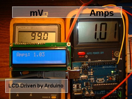 |
These photos show the same basic circuit as we used previously except the voltage across the 0.01 Ohm resistor now goes to the input of the AD623 amplifier. Still with 1 amp flowing, the output from the amplifier is 100mV - ie a x10 increase.
Supplying the AD623 with 5 volts is no problem because it only requires a few milliamps from the Arduino's 5v supply.
Example using the ByVac VT100 Serial LCD Controller.
#include <SoftwareSerial.h>

#define rxPin 0
#define txPin 2

 SoftwareSerial lcd(rxPin, txPin);

 int analogInputAmps = A5;

 int readAmpsADC = 0;
 float amps = 0.0;

void setup(){
   pinMode(analogInputAmps, INPUT);

   lcd.begin(9600);
   lcd.print("\r");            // Initialize VT100 Controller with 'CR').
   delay(500);
   lcd.print("\e[2J");         // Clear display (VT100 Command).
   delay(300);
   lcd.print("Ready");
   lcd.print("\e[2m");         // Cursor OFF  (VT100 Command)
   delay(2000);
 }

float fmap(float x, float in_min, float in_max, float out_min, float out_max) {
  return (x - in_min) * (out_max - out_min) / (in_max - in_min) + out_min;
}

void loop() {
   readAmpsADC = analogRead(analogInputAmps);
   amps = fabs(fmap(readAmpsADC, 0.0, 1023.0, 0.01, 5.0));
   amps = amps * 10;

   lcd.print("\e[1;1HAmps: ");        //Position cursor row 1; col 1  (VT100 Command)
   delay(200);
   lcd.print(amps);
   lcd.print("  ");
   delay(500);
}