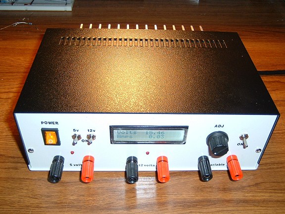
Variable DC Bench Power Supply
Design Considerations
Although my electronics workroom has a decent regulated 13.8 volts DC 10A power supply, for testing car radios and the like, and a "mish-mash" of cobbled-together 5 volt and 3.3 volt supplies for powering microprocessor type circuits, one item I've missed is a reasonable-quality variable DC power supply.When designing a power supply from scratch, there are a number of obvious criteria, such as the voltage range required and the likely maximum current capability. But there are other, less obvious, factors to consider. For example, a bench power supply in any "development" environment needs to be completely isolated from the mains supply. This means the project needs to be designed around a good quality, double wound mains transformer. Ex-PC switched-mode power supplies really aren't suitable (or safe) for this sort of application.
At the design stage, I envisage a 0 - 12 V DC 5A supply. Construction techniques and safety considerations must be the number one priority in a design such as this. Unfortunately, good quality relatively high current components are not cheap. Ready- built bench power supplies of this type are typically around 100 GBP. Using new components throughout, it's likely that the cost of this project will be similar.
For the voltage regulation, it hardly seems worth using discrete transistors these days when there are purpose-designed 3-terminal regulators available. The National Semiconductor LM338 seems to fit our needs. Although it won't adjust all the way down to 0 volts, its minimum (1.2 volts) would be fine. A quick scan through the datasheet shows that it needs a 3 volt minimum differential between its input and output voltages so a mains transformer with a 15 volts AC secondary would seem to be indicated.
When operating at a low voltage with a relatively high current, the LM338 will need to dissipate a lot of surplus energy so a large heatsink will be required. Without detailed data on the heatsink I'll be using there'll need to be some trial and error.
The Transformer
Looking through the lists of suppliers' transformers, there's a big price jump between transformers with a 12 volt 4A output and those with 15 volt 5A outputs. I can quickly come to the conclusion that a 4A transformer would be more than adequate for my requirements but do I really need a 15 volts AC output in order to get the 3 volt DC differential required by the LM338 for my 12 volt maximum output? The answer depends on the type of rectification I use and whether the transformer's datasheet is being entirely honest....
Rectification
There are basically three different circuit arrangements to convert the AC from the transformer secondary winding to DC. The scheme we choose depends on the type of secondary winding.
 |  |
|
 |  |
 |
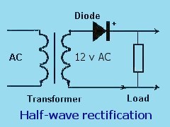
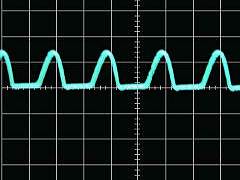
The top images show the AC voltage output using a single diode. Only half of the full AC cycle is used resulting in a very 'lumpy' DC output. OK for cheap battery chargers but a decent bench supply needs to do better.
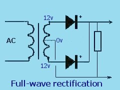
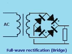
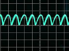
In the lower images, both halves of the AC cycle contribute to the DC output. The first, using two diodes, requires a transformer with two secondary windings which are connected in series or a secondary with a centre-tapped winding. The second uses four diodes in a bridge configuration but only requires a transformer with a single secondary winding. The output waveform is the same in both cases but the first method is more efficient in that the power dissipated by the secondary is shared between the two windings. Also, with the first method, output voltage is only lost across one diode whereas, in the bridge connection, the voltage dropped across two diodes has to be taken into account.
The transformer I had intended to use provides just 12.5 volts off load and has a single winding. The AC voltage is measured as the "RMS" value and, after using a bridge rectifier, the DC voltage is closer to the "peak" value. So, after rectification, I'd expect to see about (12.5 x 1.414) - (2 x 0.7) volts DC. Just over 16 volts is comfortably above the 3 volt input-to-output differential required by the LM338 regulator for a 12 volt maximum ouput. Unfortunately, the on-load voltage is a different story...
Regulation
Regulation is a measure of the difference in voltage provided by the transformer's secondary winding when it is on load and off load. It is expressed as a percentage relative to the full load voltage and, basically, the lower the value, the less the voltage difference. Strictly speaking, the transformer's datasheet (or supplier) should state the output voltage when the transformer is under its full rated load.For example, a transformer rated at 12v, 50VA should provide 12v to a load which takes 4 amps. (50VA at 12 volts = 50/12 = 4.1 Amps). My transformer provides 12.5 volts off load so, unless the regulation is exceptionally good, the "nominal" 12 volts hasn't been specified as the on-load voltage at all.
                (off load voltage) - (on load volatge) x 100
%Regulation =   -------------------------------------------
                             (on load volatge)


                (12.5 - 12) x 100
            =   ------------------
                       12

            =   4%  <---- This seems unlikely!
Later tests proved that the output voltage dropped to less than 11.4 volts when presented with a load of just 2 Amps. At best,
this is a regulation of around 14% even at just 2 Amps. I've now selected this transformer from Rapid Electronics. Its regulation is specified as 9% so, even if the 15 volts output specified (7.5 + 7.5) is at a low (or no) load, there'll be more voltage "in reserve" to provide the 3 volt differential required by the LM338 voltage regulator. Although still 50VA, it's now at 15 volts (instead of 12v) so the maximum current is now only 3.3 amps. But that will be the transformer's continuous rating so will probably be able to supply closer to 4 amps for short periods..
The disadvantage of using a transfromer with too high an output voltage is that the LM338 regulator will need to work harder and dissipate even more surplus energy and, as the maximum off load votage will be higher, the voltage monitoring circuit will need to take the higher voltage into account.
Using a transformer with two 7.5 volt secondary windings would allow for the input voltage to the bridge rectifier to be switched to provide two separate voltage ranges, ie 7.5 or 15 volts. Although this would ease the heatsink demands of the LM338, I didn't feel the added complication of the switching was justified given my (normally) modest current requirements - particularly at lower voltages.
When I tested this transformer, it provides around 20 volts off load and over 16 volts at 2 Amp so its specifications are correctly stated under full load conditions although a regulation of 9% at full load seems doubtful.
The Circuit
Safety Considerations
This project uses potentially lethal mains voltages and comparatively high currents. Do NOT skimp on safety arrangements such as earthing (grounding), fuses, ventilation and preventing access to live parts through ventilation slots.
Use good quality screw-in type panel fuses and ensure that the design is such that, when removing the fuse holder, it is well clear of live internal contacts before there is sufficient clearance to be able to touch the fuse (or the holder's metal parts) with your fingers.
The mains earth (ground) lead is connected to the enclosure through the transformer mounting bolt.
Note that any parts of the enclosure that are attached separately (such as the front & rear panels and the top attached with self-tapping screws, for example) should have their own earth wire back to the same transformer mounting bolt. Do not rely on the self-tapping screws for earth continuity. Try to leave the incoming earth conductor longer than the live and neutral conductors so that, if the cable does get forcibly pulled, the earth will be the last conductor to break.
All exposed mains-voltage connections - to the illuminated switch, the fuseholder and the transformer - must be insulated with heat-shrink sleeving and/or access prevented with insulating covers. It should not be possible to make contact with any high voltage connections - even with the top cover removed - without a determined and conscious effort!
The mains cable entering through the rear panel must be protected from chafing with a rubber grommet and the cable must be clamped against moving inside the enclosure to prevent the connections being pulled or twisted and to prevent the grommet being pulled from its hole. Don't knot the cable because (a) it doesn't stop the cable twisting, (b) the conductors are forced with great pressure towards each other through their insulation which can damage the insulation over time resulting in the conductors shorting and (c) it looks so unprofessional!
Despite what commercial products may do, do not use the printed circuit board for any mains voltage part of the circuit.
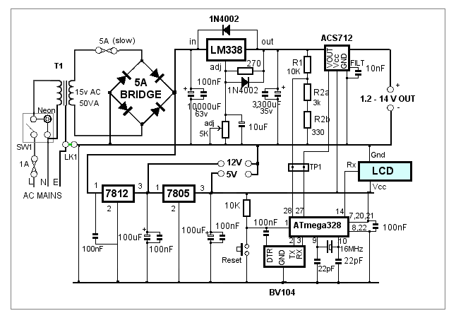
The transformer secondary winding supplies the 5A bridge rectifier via a 5A slow-blow fuse. Should the rectifier or 10,000uF smoothing capacitor become faulty and short-circuit, the fuse should protect the transformer. Other components are, I think, more likely to fail open-circuit.
The link shown as LK1 is made from two terminal posts mounted on the rear of the enclosure. The posts are normally linked so as to ground the power supply's negative (0v) rail. In case there is a rare situation in which the 0v rail needs to be floating (isolated) from ground, the link can be removed without compromising the mains supply grounding.