FM Transmitter - Car MP3 Player
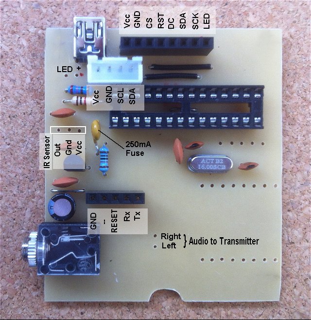
The Printed Circuit Boards
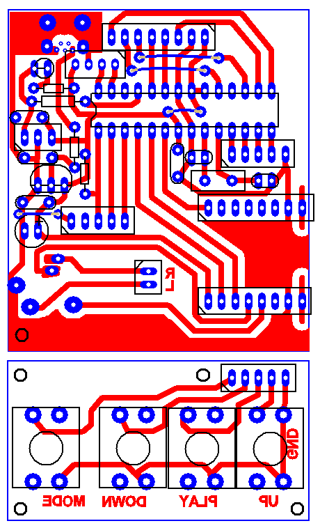
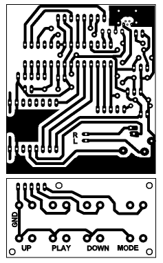 | Download actual size artwork in PDF format. |
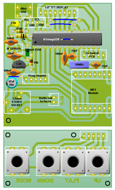
Construction
The white socket near the mini-USB socket is for Vcc, GND, SCL and SDA to the matching connector on the FM transmitter module. I used a JST socket which has a slightly lower profile than the standard PCB header connector to keep it clear of the underside of the TFT display. Note that, because of the PCB layout, the pins are not in the same order at the connector on the FM transmitter.
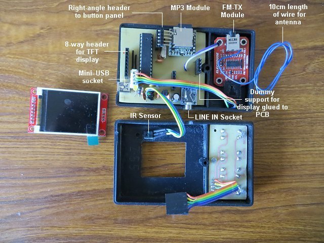
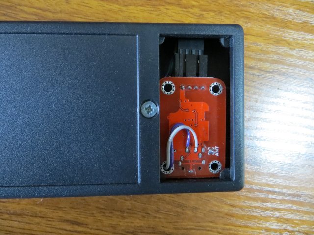
The transmitter is a snug fit in the lower half of the redundant battery compartment and the push button panel is held in the top half of the battery compartment with three 2mm screws Araldited inside the case.
The enclosure is approximately 104mm x 64mm x 28mm (external). eBay search "Plastic Project Box Enclosure Type Z55"

The FM transmitter is supplied with a 3.5mm audio socket (complete with a patch lead) but, as there isn't enough space in the enclosure to use the 3.5mm socket, the Left and Right audio inputs are soldered to the back of the FM transmitter module as shown below.
Version v1.0 of the FM transmitter incorporated a built-in microphone (which was de-activated when the patch lead was plugged in). Version v1.0 modules will need this microphone unsoldering. Version 2.0, which I received, no longer has the microphone fitted anyway.