Game-Set:
15 Puzzle, Minefield, Lunar Lander & Draughts-ish
I set out building this project with a few clear objectives:
- To use up one of my spare Nokia 5110 LCD displays. I seem to have aquired quite a few!
- To have a play with the ATmega328 in PowerDown mode. In PowerDown mode, the entire circuit uses about 18uA of which
about 2uA are taken by the voltage regulator.
- To try the MICROCHIP - MCP1702-3302E. This is a very low dropout 3.3 volt regulator so a 9v PP3 used to power the game should be good down to about 3.5 volts at the 7mA current used by the game. In addition, it has a very low quiescent current - typically 2uA.
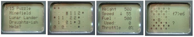
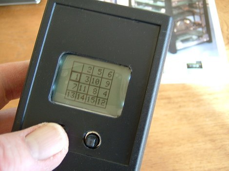
The version of 'Game-Set' presented here incorporates the 15 Puzzle (shown in the photo at the top of the page), Minefield, Lunar Lander and a very poor implementation of Draughts (checkers).
I wrote all of these games some time ago for the Amateur Packet Radio network to try and reduce the amount of 'flak' the 'frivolous' use of HTML in packet messages was getting and those JavaScript versions can be found elsewhere on my site.
Porting them across to Game-Set and particularly to the relatively small Nokia 5110 display proved to be a bit of a challenge. As games go, by modern standards, they're pretty useless but it was fun building the project in time for Christmas!
I'll begin with the construction and then, as there is very little space on the Nokia screen to display decent game instructions, I'll deal with the software and how to 'drive' it from the users' perspective.
The Circuit
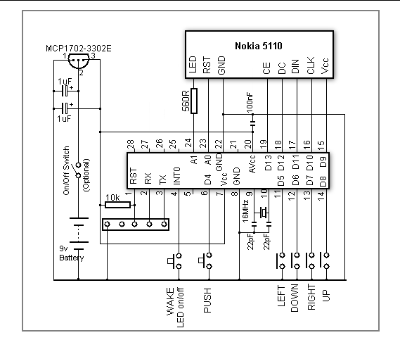 The circuit is powered with a 9v PP3 battery regulated to 3.3 volts
with the MCP1702-3302E very low dropout regulator.
The circuit is powered with a 9v PP3 battery regulated to 3.3 volts
with the MCP1702-3302E very low dropout regulator. The software is designed to put both the ATmega328 and the Nokia 5110 display into Power Down mode after 60 seconds of inactivity when the current consumption drops to only 18uA.
It's, therefore, debatable whether an on/off switch is required at all but I included one just in case!
Switches Left, Down, Right, Up and Push are a 5-way Navigation Switch from CPC. Their datasheet isn't very helpful with regards to the pin-out but there's a better datasheet here.
The Wake/LED switch is a conventional 6mm tactile switch. It's connected to the ATmega328 INT0 pin as it's necessary to use an interrupt to awake the chip from its full Power_Down mode. If the ATmega328 is powered down, pushing the switch will awaken it. If it is already awake, pushing the switch will toggle the Nokia backlight on and off.
All of the inputs have their internal pullup resistors enabled in the software to simplify the PCB layout. Although using external pullups instead would pare a few extra microAmps off the power down current, I didn't consider it worthwhile. The largest saving in power down current is achieved by disabling (in software) the ATmega328 ADC circuitry. Pins A0 and A1 are used as digital outputs as they're on the more convenient side of the ATmega328 for the PCB layout (besides there only being one spare Digital I/O pin on the other side anyway).
The Nokia 5110 Vcc supply and its LED backlight are connected to ATmega328 output pins to allow it to be powered down with
the ATmega328.
The ATmega328 Reset, Rx and Tx pins, together with a ground connection, are brought out to a header for use with an external programmer, if required.