Programming the ATMEL ATmega328
The Arduino IDE
If you're already familiar with the Arduino, you'll probably already have its programming/editing software. If not, you'll need to download and install the Arduino IDE from the main Arduino website.
If you already have an Arduino Uno, the simplest way of programming our ATmega328 is to temporarily replace the one in the Uno.
Altenatively, these articles elsewhere on my site, may help:
Making a stand-alone ATmega328 board.
Making a USB programming lead.
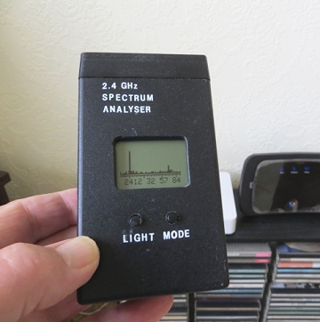
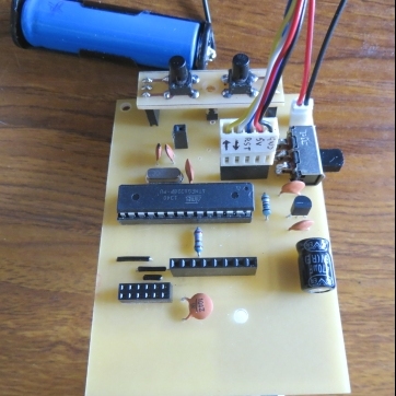
The programming header on the spectrum analyser's PCB facilitates the use of such a programming lead allowing the ATmega328 to be programmed while plugged into the spectrum analyser's PCB - and running on its own battery. The programming header on the analyser PCB deliberately does not pick up 5 volts from the programming lead but it's a wise precaution, while programming the ATmega328, to remove the radio module and Nokia display both of which are much happier running at 3.3 volts.
The ATmega328 Software
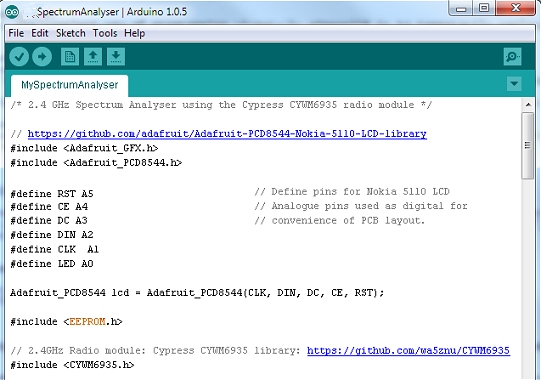
The Arduino Sketch uses three additional libraries which can be downloaded from the two web links shown in the sketch below. There is a useful tutorial here detailing how to install these libraries into the Arduino environment.Highlight & copy the code below, paste it into the Arduino IDE and upload it to the ATmega328.
/* 2.4 GHz Spectrum Analyser using the Cypress CYWM6935 radio module */

// https://github.com/adafruit/Adafruit-PCD8544-Nokia-5110-LCD-library
#include <Adafruit_GFX.h>
#include <Adafruit_PCD8544.h>

#define RST A5                           // Define pins for Nokia 5110 LCD
#define CE  A4                           // Analogue pins used as digital for
#define DC A3                            // convenience of PCB layout.
#define DIN A2
#define CLK  A1
#define LED A0

Adafruit_PCD8544 lcd = Adafruit_PCD8544(CLK, DIN, DC, CE, RST);

#include <EEPROM.h>

//  2.4GHz Radio module: Cypress CYWM6935 library: https://github.com/wa5znu/CYWM6935:
#include <CYWM6935.h>

#include <SPI.h>

#define RADIO_RESET 8                       // Radio reset pin
#define RADIO_SS 9                          // Radio chip-select pin
#define RADIO_PWR_DOWN 10                   // Radio power-down pin

#define modeButton 7                        // Set display mode button pin
#define ledButton 2                         // LCD backlight button

#define CLOCK_RADIO SPI_CLOCK_DIV128        // SPI clock divisor. 16 MHz div 128 = 125 KHz

// From 2400 to 2484 MHz. Wifi channels 1 - 1 MHz to 14 + 1 MHz
#define NUM_CHANNELS 84

CYWM6935 radio(RADIO_RESET, RADIO_SS);

byte maxArray[85];                              // Array to save peak values
byte plotMode = 0;
byte Mode_Save = 0;                             // Save mode in EEPROM
byte contrast = 55;                             // LCD contrast
boolean light = false;                          // Active low LCD LED

void setup()  {

    pinMode(RST, OUTPUT);                        // Define LCD pins as OUTPUTS
    pinMode(CE, OUTPUT);
    pinMode(DC, OUTPUT);
    pinMode(DIN, OUTPUT);
    pinMode(CLK, OUTPUT);
    pinMode(LED, OUTPUT);

    pinMode(RADIO_PWR_DOWN, OUTPUT);
    digitalWrite(RADIO_PWR_DOWN, HIGH);            // Power up radio.

    pinMode(modeButton, INPUT);
    digitalWrite(modeButton, HIGH);              // Enable internal pullup

    pinMode(ledButton, INPUT);
    digitalWrite(ledButton, HIGH);              // Enable internal pullup


    ADCSRA = 0;                                  // Disable ADC.

    SPI.begin();                                 // Initialise SPI
    SPI.setClockDivider(CLOCK_RADIO);            // Set SPI parameters
    SPI.setBitOrder(MSBFIRST);
    SPI.setDataMode(SPI_MODE0);

    radio.init();                                // Initialise Radio registers

    digitalWrite(LED, light);                     // LCD Display ON.
    delay(5);

    lcd.begin(contrast);                         // Initialize Nokia display
    lcd.clearDisplay();
    lcd.display();

    plotMode = EEPROM.read(Mode_Save);           // Get plot mode from EEPROM.
    if (plotMode > 3) {                          // If value is invalid, set to
      plotMode = 0;                              // default value and
      EEPROM.write(Mode_Save, plotMode);         // save value in EEPROM
    }
}

void loop() {

    if (digitalRead(ledButton) == LOW) {
      light = !light;
      digitalWrite(LED, light);
      while(digitalRead(ledButton) == LOW);
    }

    if (digitalRead(modeButton) == LOW) {        // Select between plot max value
      plotMode++;
      if (plotMode > 3) plotMode = 0;
      while(digitalRead(modeButton) == LOW);     // Wait for button to be released.
      delay(100);
      if (plotMode != EEPROM.read(0) ) {         // Only write to EEPROM if value has
         EEPROM.write(0, plotMode);              // changed to avoid unnecessary writes.
      }
    }

    lcd.clearDisplay();                          // Clear LCD
    for (int i=7; i<85; i+=5) {                  // Draw scale at bottom of LCD
      lcd.drawLine(i, 38, i, 37, BLACK);         // Scale minor tick marks
    }
    lcd.drawLine(0, 37, 84, 37, BLACK);          //
    lcd.drawLine(12,40, 12, 37, BLACK);          // Draw scale's major tick marks at 1,
    lcd.drawLine(32,40, 32, 37, BLACK);          // 5,
    lcd.drawLine(57,40, 57, 37, BLACK);          // 10,
    lcd.drawLine(77,40, 77, 37, BLACK);          // and 14.

    lcd.setCursor(6, 41);
    if ((plotMode == 0) || (plotMode == 1)) {    // Draw either wifi channel numbers
      lcd.print(" 1  5  10  14");                // or approximate frequency (GHz).
    } else
      lcd.print("2412 32 57 84");

    for (byte i=0; i <= NUM_CHANNELS; i++) {     // Get Signal Strength for each 1 MHz
      byte n = radio.RSSI_peak(i, 2);            // radio channel between 2401 MHz and
      lcd.drawLine(i, 35, i, 35-n, BLACK);       // 2484 MHz and plot it on LCD.

      if ((plotMode == 1) || (plotMode == 3)) {
        maxArray[i] = max(maxArray[i], n);       // Plot pixel at peak value if requested.
        lcd.drawPixel(i, 35-maxArray[i], BLACK);
      }
    }

    lcd.display();                               // Update LCD
    delay(200);

}