Controlling Arduino Outputs with the PC
Elsewhere on my website, I show details of a Video Switcher which can be controlled using the computer's parallel port. Unfortunately, fewer PCs are fitted with parallel pors these days and, for a laptop, it's not really an option.A recent failure of the PC I used to operate the Video Switcher meant I needed to find an alternative to the parallel port. Although the software I ran on the PC to control the Video Switcher is beyond the scope of this article, I needed to update it to use USB instead of the parallel port. I had in mind something similar to the Velleman K8055 USB Experiment Interface Board but without any inputs or LEDs or buffering or Analogue IO.
The original Video Switcher design only needed three data output lines from the PC's parallel port to selelct the cameras, so this seemed like a good opportunity to bring together a few bits and pieces and 'concepts' that I'd been thinking about for the Arduino; specifically:
- To build a 'minimal' stand-alone Arduino on its own PCB (Stand-alone Arduino).
- To interface the 'DIY' Arduino with either a Sparkfun Breakout Board for FT232RL USB to Serial or a ByVac Low Cost USB to Serial board -- or even try both!
- To write a simple Windows application (in Delphi) to control the 'Arduino' digital output pins, similar to the application supplied with the Velleman USB Interface. As this will be using the existing Arduino IDE's Virtual COM port, it should be much easier to write than grappling with the Velleman K8055 DLL methods and procedures!
- Ultimately (outside the scope of this article) to incorporate what I learn into the Video Switcher to act as a "bridge" between USB and the original parallel port input.
 |
|
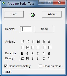
The Delphi software simply calculates the decimal number based on which checkboxes are checked and sends the number as a text string to the USB port - which the Arduino & IDE has already configured as a Virtual COM Port (VCP). Delphi doesn't have any native COM port functions or procedures and Delphi programmers will have their preferred software or 3rd Party component so I won't give the code here. I use the TComPort Library available at sourceforge.net.
It should be easy enough to write to individual Arduino digital pins rather than addressing an entire port but, in order to do this, the PC application would need a 'pin map' of the Arduino and would need to take care to read the port to which the digital pin belongs and logical OR it with the idividual digital pin's bit in order not to change the state of any of the other bits before writing to the port. For simplicity, that's not the approach I used with this current application.
The Arduino Sketch
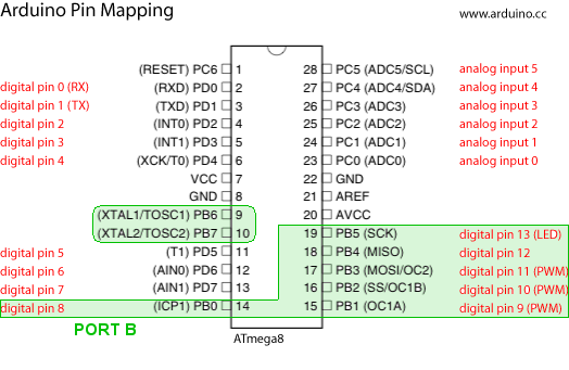
The Arduino sketch begins by setting all but the top two bits of PORTB as outputs and turning all outputs to OFF. The main loop() simply loops and builds up a String variable (inputString) when the Delphi application sends any data. The text string is converted to a numerical value and is then applied to the PORT B register.
/* This sketch receives a text string via the serial port as a numerical
   value and sets the lower 6 bits of Port B accordingly (digital pins
   13, 12, 11, 10, 9 and 8)
 */

String inputString;
int val;

void setup() {
  DDRB = B00111111;               // Pins 8 to 13 are outputs (14 & 15 are for 16MHz crystal)
  PORTB = 0;                      // All outputs OFF
  Serial.begin(9600);
}

void loop() {
  inputString = "";               // Clear inputString
  while (Serial.available()) {
    char digit = Serial.read();   // Read one byte from serial buffer
    inputString += digit;         // Add new character to the string inputString
    delay(2);                     // Let the serial buffer catch its breath.

    val = inputString.toInt();    // Convert inputString into a proper number
  }

  PORTB = val ;                   // Set PortB register bits.
}
The Delphi Source Code can be Downloaded here (Delphi 7).