The Printed Circuit Board
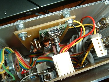
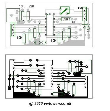
This circuit could easily be built on a piece of Veroboard (stripboard) but, for anything other than "quick and dirty" projects, I prefer to use a PCB. To me, designing and making the board is part of the building process in that it replaces the "chassis-bashing" and point-to-point wiring that I grew up with! As with the Video Switching board, the PCB layout for this board is also hand-drawn in Paintshop Pro, so check any pin spacing yourself and don't just copy this board exactly.The apparently empty pads at the right hand side of the board (component side view) are for the various switches on the front panel. As they connect directly to the pins on the PICAXE-18M2 chip, it's easy to work out which is which. Two +5 volt wires are taken from the two solder pads at the bottom right hand corner of the board (component side).One loops between the switches' common connections and the potentiometer on the front panel. The second is taken to the push button switch on the rear of the case.
Click here for a larger layout view
The two wire links at the top of the board (going to the 'output' header) are to allow data lines D1 and D2 to be crossed over to match the input data header on the video board. The same thing could be accomplished by crossing the two wires in the inter-connecting lead between the two boards but the cable would not then be reversible.
Special Parts
- PICAXE-18M2 Microcontroller
- Special USB programming cable
- 3.5mm Stereo PICAXE programming socket
- Programming Editor software (Free Download). You'll also find the necessary USB cable driver software on the same page.
The USB cable is specially made and includes a small USB-serial circuit fitted in the USB's moulded plug. As an alternative, an RS232 programming cable is available instead. The other end of both cables terminaltes in a standard 3.5mm stereo jack plug but it's important to note that the plugs (and the programming socket on our PCB) are not wired conventionally. The barrel (sleeve) of the plug is NOT the ground connection.
For that reason, I'd recommend that you buy the PCB-mounted programming socket together with the special programming cable when you order the PICAXE-18M2 chip.
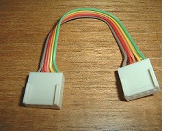 Take care to mount the three male 5-pin header plugs to both PCBs with their locating 'keys' as shown
in the PCB layout drawings. Then the female header plugs on the short loop between the two PCBs will be wired pin 1 to pin 1 and so on
and the cable will be reversible. This will prevent the cable being connected the "wrong way round" with the risk of getting 0v and +5v
crossed on the PICAXE board.
Take care to mount the three male 5-pin header plugs to both PCBs with their locating 'keys' as shown
in the PCB layout drawings. Then the female header plugs on the short loop between the two PCBs will be wired pin 1 to pin 1 and so on
and the cable will be reversible. This will prevent the cable being connected the "wrong way round" with the risk of getting 0v and +5v
crossed on the PICAXE board.
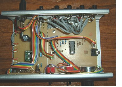
The switching/timing board can now be fitted to the case and connected to the video/display board. All that remains to do is wire
up the rear panel push button and the front panel switches and potentiometer. Make sure the wires to the potentiometer are connected
correctly as it's not immediately obvious from the layout of the pads on the PCB.
 Inside view of the completed video switcher, with the PICAXE circuit board fitted
and connected to the video/display board.
Inside view of the completed video switcher, with the PICAXE circuit board fitted
and connected to the video/display board.
With everything wired up and the two boards connected together, the software can be downloaded into the PICAXE chip using the Programming/Editor software...
The program code I used is shown on the next page. Although I've been programming in Borland Delphi (Pascal) and C for more years than I care to remember,
this version of BASIC is new to me so I'm sure the code can be improved upon. And what could be simpler than simply plugging in the
USB programming cable and downloading another attempt! The manufacturer claims the chips can be re-programmed over 100,000 times
so I should get the code perfect eventually!
 | UPDATE! (Jan 2012) I recently fitted a board to control the video from a USB socket instead
of the parallel port. See USB Control and
Arduino
|