Part 5 ~ Final Assembly & Calibration
Front Panel Template
Creating the front panel for DIY projects is always a bit of a challenge. For this project, I tried something different:I printed a mirror image of the panel layout using a laser printer and ironed it onto the thoroughly cleaned and de-greased aluminium front panel - in a similar way to making a printed circuit board etch mask. I followed it with a couple of coats of clear varnish. It isn't perfect by any means but it did allow for some flexibility in font size - which rub down lettering, for example, doesn't really allow.
I designed the panel layout using a free program called Front Panel Designer which makes positioning the labels easy.
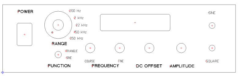
Download front-panel template mirror image
Download Front Panel layout in Front Panel Designer Format
Download Free Front Panel Designer program
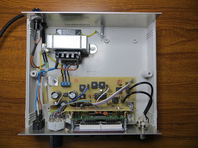
General Views
The enclosure is a Hammond 1598D which I found on eBay.The 3mm thick red transparent acrylic sheet was also from eBay. Cut a couple of millimetres larger than the panel cut-out and super-glued to the front panel. I retained the protective plastic film on the rear face as it obscured the individual unlit segments of the 7-segment LEDs but allowed the illuminated digits to shine through well.
The display board itself is attached with long M3 screws with their heads Araldited to the front panel and M3 nuts run down the threads to position the 7-segmet displays to be just touching the back of the acryllic.

The front and rear panels both have mains-voltage components and MUST be earthed (grounded) to the same transformer mounting bolt as the incoming mains earth wire. Heat shrink sleeving covers exposed mains-carrying connections as much as is practicable.
Although the mains transformer runs fairly cool, I drilled a few rows of 1mm diameter holes in the rear panel (using an old piece of Veroboard as a drilling template).
Calibration
- Connect the Sine wave output to an oscilloscope and allow the function generator and the oscilloscope to warm up for about 15 minutes.
- On the function generator, switch SW2 to SINE, turn the DC OFFSET (VR4) to the central position and AMPLITUDE (VR3) fully
clockwise (maximum).
- Set the Sine Amplitude preset (R15) for a peak-peak voltage on the 'scope of 10 volts.
- Switch SW2 to TRIANGLE and set the Triangle Amplitude preset (R16) for a peak-peak voltage on the 'scope of 10 volts.
- Switch SW2 back to SINE output. Set the 'scope input to DC and the DC OFFSET (VR4) to the central position, then adjust the DC OFFSET TRIMMER (R14) until the waveform is vertically central about 0v.
- Adjust the DISTORTION (R5) and SYMMETRY (R17) trimmers alternately for minimum distortion of the sinewave viewed on the oscilloscope.
- Repeat all the steps at various frequencies to find the best overall settings.