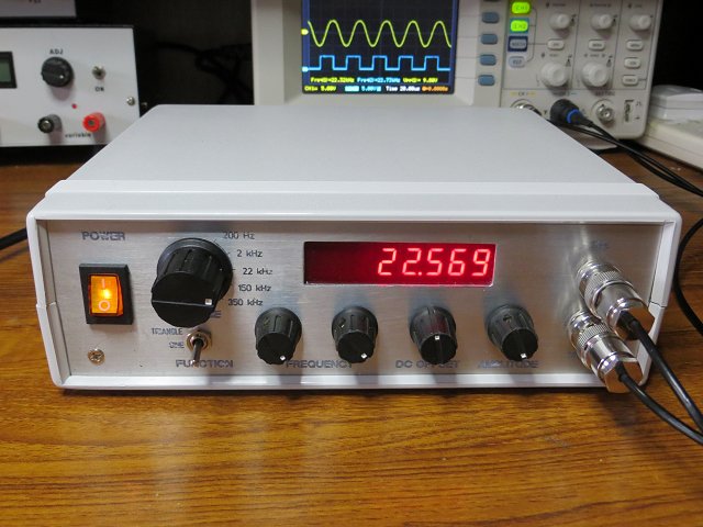
XR-2206 5Hz to 300kHz Function Generator
After making a couple of waveform generators based on Direct Digital Synthesizer (DDS) chips ( AD9850 Waveform Generator & AD9833 Waveform Generator ) I wanted to build something which uses an older 'analogue' function generator IC. There are two main contenders - the Intersil ICL8038 and the Exar XR-2206. Although neither chip is in current production, both are still widely available - either as old stock or, perhaps, as 'clones'.
Although I've seen circuits and even commercial project kits claiming several MHz frequency range, in practice I think somewhere around 400kHz or 500kHz maximum frequency is more realistic for these ICs while still maintaining a reasonably low-distortion sine waveform. For this project, I was more interested in producing a clean undistorted sinewave rather than pushing it to the limits in terms of frequency.
After breadboarding both the XR-2206 and the ICL8038, I decided to build a decent function generator using the XR-2206.
Although this is an analogue IC, this project just made it into the Arduino section of my website because it uses an ATmega328 as a frequency counter and to drive an 8-digit 0.36" LED SPI module (although only 6 digits are used).
Part 1 ~ The Function Generator

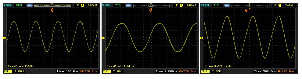
The circuit around the XR-2206 is based on the ExarTAN-005 XR-2206 Application Note which describes a "High quality 1Hz to 100kHz function generator." After playing with some of the component values and adding a couple of OpAmps, I think the sine wave quality is acceptable up to 550kHz although the triangle wave starts to get rounded peaks at around 300 kHz.
Frequency control
The frequency range is controlled with the timing capacitor (connected between pins 5 and 6 of the XR-2206) and the timing resistors VR1, VR2 and R2 (conencted in series between pin 7 and -12v). With the component values shown above, the overlapping frequency ranges are shown in the following table: The overlapping of the ranges isn't ideal but it hasn't proven to be a problem in practice. The TAN-005 Application Note recommends a log-taper for the frequency adjustment (VR1) although I've used a linear one and added the "fine" frequency control (VR2).
| Capacitor | Minimum Frequency | Maximum Frequency |
|---|---|---|
| 1uF | 2.25Hz | 225Hz |
| 0.1uF | 20Hz | 2kHz |
| 0.01uF | 225Hz | 22kHz |
| 0.001uF | 2.0kHz | 186kHz |
| 470pF | 4kHz | 375kHz |
The Exar XR-2206 datasheet recommends 1000pF (0.001uF) as the minimum value for the timing capacitor connected to pin 5. I've found that the square wave, in particular, tends to become 'jittery' and unstable between approximately 23kHz and 50kHz with a timing capacitor smaller than 400pF. As I'm using the square wave output for the frequency counter/display, I've limited the smallest capacitor to 470pF which results in a top frequency around 375kHz. If the capacitor is reduced to 100pF, the highest frequency is around 500kHz still with acceptable waveforms - except for the jittery square wave and resulting unstable frequency display between 23kHz and 50kHz.
Output Amplitude
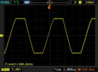
Selection between sine and triangle waveforms is accomplished with switch SW2b connected across XR-2206 pins 13 and 14. When the switch is closed, the output is a sine wave. With the switch open, it is a triangle wave.Unfortunately, the output voltages of the sine and triangle are not the same. The maximum sine wave is about 6 volts peak-peak and the triangle wave is about twice that. In my circuit, I've added two pre-set trimmers - R15 and R16 - to adjust the waveforms so they're the same voltage. When SW2b is closed, the output is a sine wave and SW2a connects R15. When SW2b is open, the output is triangle and R16 becomes the 'active' pre-set.
R15 and R16 both need to be "backed off" from maximum otherwise the TL027CP OpAmp is overloaded when the main Amplitude control - as part of the TL072CP circuit - is turned to maximum. Once R15 and R16 are set correctly, the output from the TL027CP is fully adjustable from near zero to about 10 volts peak-peak (ie ±5v about the centre ground 0v). Although about 20 volts peak-peak can be achieved, 10 volts peak-peak is preferable to avoid excessive clipping when DC OFFSET is applied.
This image shows the effect of having the sinewave's Amplitude preset trimmer set too high.
DC Offset
R14, which is connected to the XR-2206 via R1, is used to set the DC Offset of the waveforms. As the circuit uses a split power supply ( ±12v), R14 can adjust the waveform's centre to be slightly positive or negative of ground. In practice, the amount of adjustment is fairly limited so I've used R14 as a pre-set trimmer instead. The Sine/Triangle output on pin 2 of the XR-2206 is connected to a TL072CP OpAmp which has its own DC Offset adjustment via VR4 so the pre-set trimmer R14 is only used to"centralise" the adjustment of VR4 - ie the waveform is centred about 0v when VR4 is centred.
The TL072CP
The first half of the TL072CP OpAmp (IC3a) is used as a unity-gain buffer . IC3b provides about 5.7x gain [ (R12/R13) +1 ] and a wide DC Offset adjustment.Choice of the TL072CP was quite critical. Initially, I used an LM6172 which has a better frequency response but I found I could get a higher un-distorted output frequency using the TL072CP. As the chip is socketed on the PCB and OpAmps tend to be pin-compatible, it's easy to try different ICs.
The Sync/Square wave Output
The XR-2206 provides a separate output for the sync/square wave and it's virtually a rail-to-rail output at over 20 volts. It's useful for synchronising the oscilloscope while probing a circuit with the sinewave but I also wanted to use it to drive a frequency counter. In either event a more manageable output voltage seemed sensible. R6, R7 and R8 provide an 8v peak-peak signal with about -0.1 volts below ground.This signal is fed to both halves of the comparator - LM293. The outputs at pins 1 and 7 swing between ground and 5 volts. The output on pin 7 is taken to a front panel BNC socket (for 'scope sync or other uses) and the output on pin 1 is taken to a header - together with +5v and ground - for connecting to the ATmega328-based frequency counter. The 1N4148 helps protect the ATmega328 input by removing any negative spikes that may be present on the square wave.
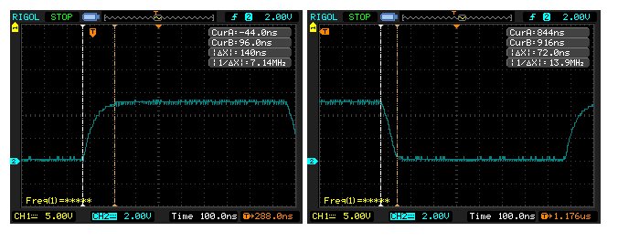
At 590kHz, the square wave has a rise time of about 140ns and a fall time around 70ns. A faster comparater could be used if faster rise and fall times are required. However, as I've noted above, I've restricted the upper frequency limit to about 310kHz because of the square wave's instability between 23kHz and 50kHz when using the smaller timing capacitor.