Soldering in the components
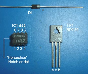
 The photograph to the right shows the other components which must be inserted the correct way round to avoid destroying them. The diode shown does not have the same colouring as the one used in the project but the positive (+) end will be marked with a different-coloured band. |
Solder in the other components checking that they are inserted the right way round where necessary. R1, R2, R3, C1, C2, the speaker (LS) and the On/Off switch can be soldered either way round. C3 is a different type of capacitor and has to be soldered in with the + lead connected to the +9v supply. Note that, for some reason, the legend marked on the capacitor often denotes the negative (-) lead so take care.
|
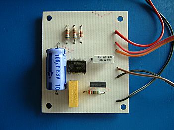
The completed project
