The Components
|
|
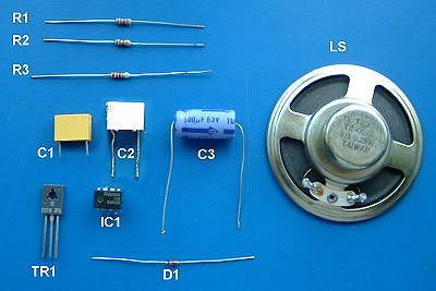
Here's the actual components we're going to use for our project and I've repeated the table we saw on the first page where we also covered all the theory we need for the resistors. R1, R2 and R3.
Let's take a look at the capacitors: C1, C2 and C3. Like resistors, capacitors also come in a vast range of values. Whereas the basic 'unit' of the resistor is the Ohm, that of the capacitor is the Farad. However, 1 Farad is huge for electronic use and micro-Farad (µF) is more common which is one-thousandth of a Farad. Even then, you'll notice that C1 and C2 are only fractions of 1 µF.
In simple terms, for the purposes of our project, a capacitor is used to temporarily 'store' an electrical voltage. The time taken for the capacitor to become "full" is determined by its value (the larger the value, the longer it takes) but also by the value of the resistor allowing the current to flow into the capacitor. Once the capacitor is "full," the current stops flowing.
Look at the capacitor values in the table. In addition to the value in µF, there is also a voltage rating shown which is not shown on the circuit diagram. The value shown in the table, is the minimum voltage rating we should use. If you look closely at the photograph, you'll see that C3 has a 63v rating. C1 and C2 will be considerably higher than this. Provided the voltage rating of the actual components is equal to or above that stated in the table, all will be well.
Soldering..
OK, enough theory for now. Let's carry on.
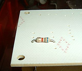
| Select resistor, R1, bend its leads at right angles and push it through its holes in the PCB. Splay the leads outwards slightly on the underside of the board to stop the resistor dropping out and turn the board over. All three of the resistors can be fitted either way round. |
|
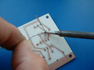
Melt a small amount of solder (about 1mm length) on the tip of the soldering iron - just enough to form a liquid layer - then
apply the tip of the iron and the end of solder simultaneously to the resistor's lead and the copper pad
on the PCB. The purpose behind forming a liquid surface on the soldering iron first, is to create a path for the heat from the iron to flow from the iron to the solder, lead and copper simultaneously. Hold everything still while the solder is flowing - don't use the soldering iron like a paintbrush - then remove the solder first, closely followed by the iron. Use only about 1mm of solder on the joint. |
|
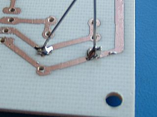
The entire soldering operation should take less than 2 seconds - preferably less than 1 second - per joint. The solder joint shown on the far left is good. It's surface is shiny and the sloping sides are slightly concave. The solder appears to flow without a step into the surrounding metals surfaces. The joint on the right is not good. See the way it looks like a "blob" - it's sides bulge out and it hasn't merged with the surrounding metal surfaces - probably because the metal wasn't clean and shiny. Gently re-apply the iron and the solder may flow better. |