Rigol DS1052E DSO ~ First Impressions and Review
 I've had my old analogue 'scope for more years than I can remember and it's still working well. In
truth, though, it has to be said that its sheer bulk means it's generally tucked away in a corner, usually with a pile of other stuff stacked on top
of it.
I've had my old analogue 'scope for more years than I can remember and it's still working well. In
truth, though, it has to be said that its sheer bulk means it's generally tucked away in a corner, usually with a pile of other stuff stacked on top
of it.
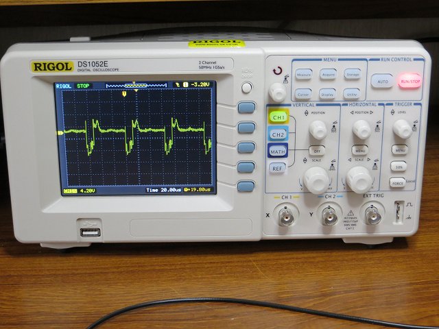
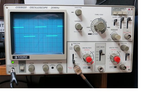
In contrast, the DS1052E DSO is only about a third of the depth although the front panels are roughly the same size. Hopefully, because it's easier to find space for it on the workbench, it should get a lot more use than the analogue 'scope.
Comparing the two front panels, it's immediately obvious that missing from the DS1052E are the scale markings around the various knobs - volts/div on the vertical axes and time/div on the horizontal axis, and so on.
Instead, the values of the knobs' settings are displayed in the bottom "status bar" on the display. In the photo above, the vertical channel sensitivity is set to 4.20V (per division) and the horizontal axis is set to 20.00µS per division.
All the knobs are rotary encoders, complete with a push button, rather than physical switches. I'm not overly convinced they're inherently any more reliable than physical rotary switches - time will tell.
Another major difference between the two 'scopes (and I must admit one that takes a little while to get used to) is that there is only
ONE set of vertical controls to adjust BOTH input channels.
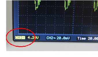 The only way to determine which channel will respond to the vertical controls is to look at the display's status bar - the "selected" channel being highlighted as shown here in the photo on the right.
It's quite straightforward in practice and trying to describe how the channels are selected would make it sound more complicated than it actually is. It's just a departure from
the way the analogue 'scope does things so it takes a bit of getting used to and does sometimes result in several button-presses before the
correct action is selected. More expensive DSOs do have separate vertical controls for each channel.
Vertical Channels Options
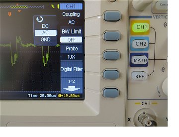 When a channel button is pressed, its menu appears on the right side of the display. Here you find the same sort of options which an analogue 'scope offers through 'physical' switches - for example Input Coupling (DC, AC, GND),
Probe (10x, 1x) and so on. Actually, probe attenuations of 1x, 5x, 10x, 50x, 100x, 500x and 1000x are available. Two probes are supplied with the 'scope, each with a 1x / 10x switch.
When a channel button is pressed, its menu appears on the right side of the display. Here you find the same sort of options which an analogue 'scope offers through 'physical' switches - for example Input Coupling (DC, AC, GND),
Probe (10x, 1x) and so on. Actually, probe attenuations of 1x, 5x, 10x, 50x, 100x, 500x and 1000x are available. Two probes are supplied with the 'scope, each with a 1x / 10x switch. Pressing one of the "soft menu" buttons (the vertical column of 5 buttons alongside the edge of the display) brings up that item's sub menu. For example, pressing the top soft menu button brings up the Channel's input coupling sub menu. The circular arrow that can be seen in the sub menu is a "hint" that the multi-function knob (the one above the channel buttons) is used to select between DC, AC and GND. Repeatedly pressing the soft menu button also steps through the options and is sometimes quicker than using the rotary knob.
The BW Limit ON | OFF menu item is useful to clean up a noisy signal. Turning it ON inserts a 20MHz low-pass filter into the input signal to reduce noise above that frequency. It seems to be a fairly standard option on modern 'scopes that my old analogue model lacks.
There's also a highly-configurable Digital Filter which can be set to clean up a noisy signal even further. It can be configured as low-pass, band-pass, high-pass or as a band-reject (notch) filter. Both upper and lower frequency cut-off points can be set. Presumably these are the -3dB points although the User Guide doesn't say.
The vertical SCALE knob adjusts the selected channel's input sensitivity. The knob uses the 1-2-5 step convention (as used on the analogue 'scope). That is, the vertical scale sensitivity can be adjusted to: 20mV, 50mV, 100mV, 200mV, 500mV, 1V, 2V, 5V, 10V, 20V, 50V, or 100V per division.
Pushing the SCALE knob once increases the resolution for fine adjustment of the vertical scale. The size of the step varies depending on the main scale setting ranging from 1.0V steps to 0.5mV steps. Pushing the knob a second time reverts to the normal 1-2-5 course setting sequence. The actual volts (or mVolts) per division is always shown on the display's status bar.
The POSITION knob adjusts the position of the display trace vertically as in an analogue 'scope. Pushing the knob is a quick way of
returning the trace to the centre (zero) position. The significance of this varies depending on whether the input is AC or
DC coupled.
The REF Button
 The REF button is used to capture and retrieve saved waveforms. It's useful to compare waveforms
directly on-screen.
The REF button is used to capture and retrieve saved waveforms. It's useful to compare waveforms
directly on-screen.
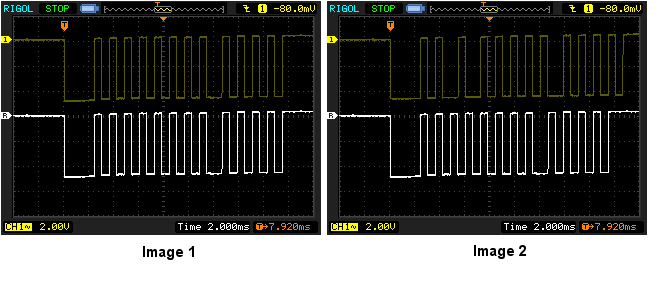
Example:
In Image 1 (far left), the yellow trace is the signal from an IR remote control when the Play button is pressed.
The white trace is an exact "clone" taken by pressing the REF button.
In Image 2, the 'scope has captured a second waveform from the IR remote control. Using the REFerence waveform makes it very easy to compare the two input signals to see whether or not they're the same. In this case, the Stop button was pressed and it can be easily seen that they not the same. Without being able to save to first waveform on screen, the comparison would be difficult.
The REF waveform can be adjusted with the vertical and horizontal controls exactly like a regular waveform.
The MATH Button
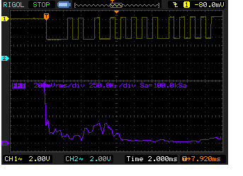 The MATH button is used, as its name suggests, to perform mathematical operations on the waveforms. Options are A+B, A-B, AxB
and FFT. I won't pretend to understand FFT (Fast Fourier Transform) except to say it uses maths to transform a waveform's usual
time domain (on the x axis) to frequency.
The MATH button is used, as its name suggests, to perform mathematical operations on the waveforms. Options are A+B, A-B, AxB
and FFT. I won't pretend to understand FFT (Fast Fourier Transform) except to say it uses maths to transform a waveform's usual
time domain (on the x axis) to frequency.FFT works on one input signal only so there's plenty of space on the display. A+B, A-B and AxB obviously use both inputs so the screen does get a bit cramped with three waveforms on the display although they are still perfectly readable.
Note the  at the left of the display is highlighted which means the FFT waveform is "selected" and
will be the waveform that responds to the vertical and horizontal controls.
at the left of the display is highlighted which means the FFT waveform is "selected" and
will be the waveform that responds to the vertical and horizontal controls.
Horizontal Options
 The horizontal controls are straightforward in normal use when the same timebase is used for both channels. The horizontal SCALE
also uses the 1-2-5 step convention and adjusts (in the 50 MHz DS1052E) from 50 seconds to 5 nSec per division.
The horizontal controls are straightforward in normal use when the same timebase is used for both channels. The horizontal SCALE
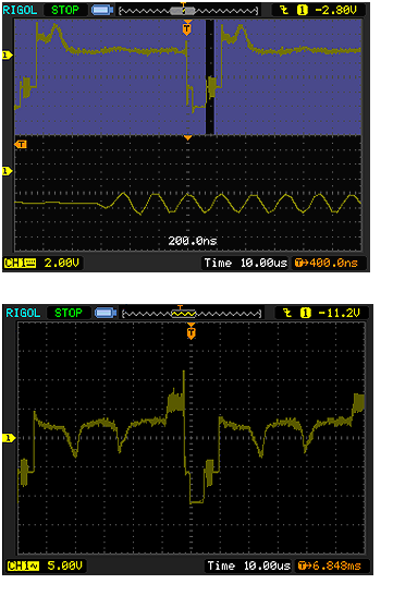
also uses the 1-2-5 step convention and adjusts (in the 50 MHz DS1052E) from 50 seconds to 5 nSec per division. Pushing the SCALE knob invokes a "zoom" function which let's you zoom in on specific parts of a waveform.
For example, the top waveform shown left shows a couple of lines from a CCTV camera. With the "zoom" function enabled, the blue "mask" lets you zoom in on a particular section of the waveform - in this case the camera signal's colour burst. It's really very similar to simply adjusting the horizontal SCALE except it allows you to see both the full waveform and the expanded section at the same time.
The POSITION knob allows you to adjust the position of the waveform horizontally as in an analogue 'scope but there is one fundamental difference: In an analogue 'scope, the spot sits patiently at the left of the screen until it's triggered by whatever triggering mechanism you've set up. The spot then moves across the screen left to right, the vertical position being determined by the instantaneous vertical input voltage at each (and every) moment in real time.
A digital storage oscilloscope, however, "waits" (sort of) at the centre of the screen and, when it gets the trigger, begins capturing vertical samples to build up
the waveform from the screen centre to the right. But, it has also been sampling the waveform before the trigger point to build up the waveform to the left of the trigger point.
The orange  at the top of the display shows where the trigger point occurred.
This is a major advantage over the analogue 'scope in that it lets you see what the waveform was doing before the trigger point not just after it. Of course, the spot isn't actually "waiting" at the centre of the screen in a digital 'scope; instead it all happens in memory and, once the memory is full of samples, then the waveform is displayed on the screen.
Trigger Options
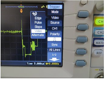 The main Trigger menu is invoked by pressing the MENU button in the Trigger section of the front panel. There are plenty of triggering Modes
in the Mode sub-menu (Edge, Pulse, Slope, Video, Alternate) each of which displays different options in the Trigger menu. The circular arrow again indicates that
you use the multi-function knob to select an option from the sub-menu.
The main Trigger menu is invoked by pressing the MENU button in the Trigger section of the front panel. There are plenty of triggering Modes
in the Mode sub-menu (Edge, Pulse, Slope, Video, Alternate) each of which displays different options in the Trigger menu. The circular arrow again indicates that
you use the multi-function knob to select an option from the sub-menu.The down arrow within the circular arrow indicates that you need to press the multi-function knob for the selection to be accepted.
Some sub-menu items automatically update the selection in the main menu as you scroll through the sub-menu options - in those cases you won't see the down arrow.
If you use the soft menu button to step through the options in the sub-menu, the main menu is automatically updated without the need to press the multi-funtion knob. It sounds complicated but it's just different ways of achieving the same result.
 One particularly nice feature is the Alternate Trigger Mode. Most analogue 'scopes have
a similar option to display two waveforms simultaneously but, in all but the very top of the range models, the waveforms have to share the same horizontal
timebase. (Dual trace rather than true dual beam).
One particularly nice feature is the Alternate Trigger Mode. Most analogue 'scopes have
a similar option to display two waveforms simultaneously but, in all but the very top of the range models, the waveforms have to share the same horizontal
timebase. (Dual trace rather than true dual beam).
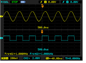
By selecting Alternate Trigger Mode, the DS1052E effectively has two sets of independent horizontal controls - much like a true dual beam analogue 'scope.
In this image, Channel 1 is displaying a 1.0MHz sine wave while Channel 2 is displaying a 1kHz square wave yet both are showing a similar number of cycles on the screen.
The top horizontal time is 500ns per division while the bottom time is 500µs per division.
The Trigger LEVEL knob adjusts the voltage point in the waveform at which triggering takes place. Pushing the knob resets the value to zero. A value which doesn't usually make much sense in itself but at least it provides a starting point if you "get lost". A 50% button forces the trigger voltage to 50% of the waveform and the FORCE button will cause the 'scope to trace a line whether it receives a trigger or not.
The Local label alongside the FORCE button is for use when the oscilloscope is connected, via USB, to the Ultrascope software running on a PC. Once that software is running, it takes over control of the DSO and most of the
buttons and knobs become ineffective. Pushing the FORCE/Local button forces the PC software to relinquish control and hand it back
to the local buttons and knobs on the 'scope.
Menu Buttons
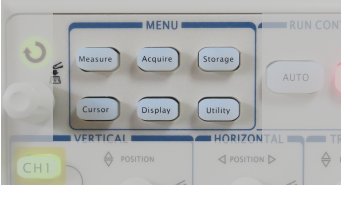
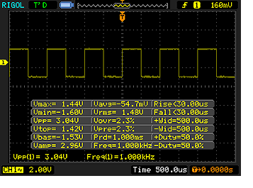
The Measure Button
This function can be used to continuously display a waveform's various parameters. Alternatively, just a few parameters can be selected.
The Cursor Button
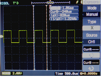
This function can be used to precisely measure waveform parameters using two pairs of cursors. By pressing the multi-function knob (or pressing the soft menu buttons), you select which cursor you wish to adjust and turn the multi-function knob to position each cursor.Alternatively, you can select which cursor you want to move using the CurA---- and CurB--- soft menu buttons.
This function is useful for both repetative and single shot waveforms. It works well and automatically displays a table showing the positions (in time) of the cursors relative to the trigger point as well as the time interval between the two cursors (ΔX). It also shows the frequency (based on 1/ΔX) which, provided you set the cursors exactly at the start and end of one cycle, gives an accurate measure of frequency.
Selecting Type Y cursors displays two horizontal cursors for measuring vertical parameters (ie voltages) in a similar way.
The other menu buttons perform functions for configuring the sample rate and type, for saving to a USB stick (most of the images above were obtained that way), printing, setting up the USB ports, the colours and brightnes used for the display etc. They're all fairly self-explanatory and intuitive.
Bitmap images or waveform data can be saved to a USB stick plugged into the front panel USB port. Saving the images is invoked by pressing the Storage button. Naming files is a bit laborious involving moving a cursor on a small on-screen keyboard with the multi-function knob but, as it's just as easy to rename the file on the PC, it's not really a big issue.
The Auto button can be useful when you are struggling to get something - anything - on the display because maybe just one or two settings are miles off. Use with care, though, because it seems to reset a lot of unnecessary settings to default values and it can easily upset some settings you've spent ages getting "just right" !
Impressions
The User Guide is supplied on disc together with the Ultrascope PC software. The User Guide is fairly comprehensive and, although the English is a little 'stilted' in places, I found it generally easy to understand. It's also available for download from the Rigol website.There's also a Service manual available for download here.
Overall, I'm very impressed with the DS1052E. It's my first digital storage oscilloscope so it's difficult to make comparisons but I can already feel I'll be using it a lot more than I use my analogue 'scope.
Not surprisingly, there have been a few firmware updates since the DS1052E's introduction but, to me, it has resulted in well-thought-out, easy to use, intuitive controls. There have been a few times when the location of a particular feature or other has eluded me but they're usually quickly found in the User Guide.
There are obviously some compromises in a DSO at this price. The screen resolution is quite low (320 x 234 pixels) for example but comparison with more expensive 'scopes would be unfair. The build quality seems excellent - for any price range - and all of the reviews I've read online are good. As with others, I'd comment on the fan which is fairly noisy - especially in an otherwise quiet hobby room when you're trying to think!
At some point I almost certainly will fit a quieter fan but, as it means breaking the "warranty void if broken" sticker, I'll live with the fan noise for now. And, when I do get "in there", I'll take a look at the LM7905 -5v regulator which is mentioned in a lot of reviews as it runs hot, has no heatsink and is somewhat "flapping in the breeze" at a crazy angle above the PCB - about the only poor bit of the entire design there is to criticise.
Update: Well, I did the fan mod but haven't fitted a heatsink to the LM7905 yet. As it's unsupported, I'm a bit concerened that the weight of a heatsink might encourage it to vibrate more. See the fan mod here.
I'm aware of a firmware modification (ie hack) which should convert the 'scope to the 100MHz model. I have no real use for a 'scope of that bandwidth otherwise I'd probably have bought one! One day, I might risk it but, as with most of these hacks found on forums, software versions get updated but the forum info doesn't necessarily keep up to date. A firmware hack that worked two years ago almost certainly won't work if the original firmware has been updated. It's a really nice 'scope that's more than adequate for my needs so I see no reason to risk bricking it.
Links
User GuideService Guide
Official Rigol Demonstration Video - Part 1
Official Rigol Demonstration Video - Part 2