Index
| Part 1 -- Non-technical stuff. | Part 2 -- Technical stuff. |
| Introduction | Aerial Checks and Selection |
| Checking your Equipment | Checking the Receiver |
| Weak Television Signal | Receiver Faults |
| Ghosting | Braid-Breakers and High-Pass Filters |
| Co-channel Reception | |
| Electrical Interference | For the Transmitting Amateur:- |
| Interference from Radio Transmitters | Questions & Answers Problem-Solver |
Introduction
Nearly half of all reception problems are due to deficiencies or faults in the television receiver, the aerial lead or the aerial. The following information will help you to check whether the problem you are having is due to one of these causes.
Portable television sets fitted with an inbuilt aerial or a set-top aerial are prone to a number of reception problems. Where these reception problems are experienced, the set should be fitted with an aerial lead and an externally mounted aerial. The following advice applies only to television sets having an outside aerial.
Checking your equipment.
- Check that your mains plug is wired correctly with the connections tight and that it is pushed firmly into the socket.
- Check that you are able to get a good steady picture at the times when the reception problem is not present.
- Ask your neighbours if they have the same or similar type of problem. Some controls on the TV set, such as tuning are not often used and can spoil viewing if they become out of adjustment.
- Check that your aerial lead appears to be in good condition, with its plug firmly attached to the lead and making good contact when pushed into the aerial socket on the back of the TV set.
- Check your aerial has not been moved with the wind. A glance at neighbouring aerials will show the correct direction.
- Check that you have the right aerial for your area. If you are in doubt, consult your local dealer or aerial installer.
- Hotels, blocks of flats and some housing estates use a communal aerial which you cannot check yourself. You should contact the landlord or his nominated contractor.
[Top]
Note about Digital Terrestrial Television
I wrote this article when digital terrestrial television (DTT) was unheard of. Although all of the principles are exactly the same, actually tracking down the source of interference can be much more difficult because the effects on the picture and/or sound are the same regardless of the type of interference - ie the picture (or part of it) will briefly break up into 'blocks' (pixelation) or it will freeze completely. Whether or not the sound is affected depends primarily on the severity and duration of the interference regardless of its type.
![]()
![]()
You can only guess at the type of interference by the severity of its effects on the picture, by it's duration and whether or not it occurs at specific times of the day. Without test equipment, it's not really possible to tell whether the receiver is susceptible to the interference because of an inherently weak signal but many DTT receivers do have a signal meter which indicates both the strength and 'quality' of the signal.
Poor signal strength would generally indicate an inadequate aerial or damaged or poor quality cable (see 'Checking Your Equipment', above). Good signal strength but poor Quality would indicate an adequate aerial and equipment but strong interference, 'Ghosting' or (less common) co-channel reception.
The methods of curing the interference - or at least reducing its effects - are exactly the same as in the notes below.
Weak television signal
 |
 |
 |
| Normal Picture | Progressively Weaker Signal | |
Each TV station has a defined service area where the strength of the TV signal is adequate to give good reception. Just beyond the boundary of the service area is a fringe area where the signal will be weaker and reception quality will be poorer.
What you can do
Once you have checked that your weak signal is not due to a defective or badly pointed aerial, or a poor condition, broken or disconnected lead, you can improve the strength of the signal by:
- Installing a better or higher aerial. (The erection of television aerials may require planning permission.)
- Installing a masthead amplifier to boost the signal.
[Top]
"Ghosting"
|
 |
 |
| Normal Picture | An example of "Ghosting" | Why Ghosting Occurs |
The problem is caused because you are receiving both the direct signal and a reflected signal from the transmitter. Because the reflected signal travels a greater distance before it arrives, it produces a picture shifted to the right of the normal picture.
What you can do
A better picture can usually be obtained by altering the direction in which the aerial is pointing. This will require someone to watch the television for the best picture while the aerial is slowly moved from side to side, up and down, or twisted.
If ghosting is severe and persistent, ask your dealer to try other aerials.
[Top]
Co-channel reception
 |
 |
| Two Examples of Co-channel Reception | |
What you can do
Some improvement can usually be gained by fitting a different aerial. Ask your dealer for advice.
[Top]
Electrical Interference
 |
 |
| Type 1 | Type 2 |
| Two Examples Electrical Interference | |
Many interference problems, however, can be traced to domestic electrical equipmentor appliances in your own home or a neighbour's.
Some causes of electrical Interference - Type 1
- Vacuum cleaners
- Fans
- Electric drills
- Electric trains
- Electric razors
- Sewing machines
This type of interference is normally caused by switches or thermostats especially thermostats in central heating systems. It appears anywhere on the screen as a dense white band of spots for a short time only.
- Automatic switches
- Central heating thermostats
- Refrigerators
- Freezers
In many cases the source, if it is in your own home, will be obvious because the interference to your TV appears when something (eg electric drill) is being used. Where the source of interference isn't immediately obvious, try to locate it by switching off in turn everything in the home while someone watches the effect on the TV screen.
Alternatively, if you have a portable radio and can hear the interference on it, take the radio from room to room to find where the interference is loudest.
All modern electrical equipment is manufactured to regulations requiring that interference suppressors are fitted. If you find that one of your appliances is causing interference and the appliance is still under guarantee, send it back with a request that it be put right. Otherwise, ask an electrical dealer to fit a suppressor to it. Under no circumstances should you attempt this internal modification yourself.
[Top]
Radio transmitter interference
Radio transmitters are used for communication by Citizens' Band enthusiasts, radio amateurs, radio taxis and many other licenced and authorised services. Strong radio transmissions from any of these sources could affect your set.
In many cases there is no fault with the radio transmitter and the radio operator is not to blame. The problem occurs because the TV set is not designed well enough to resist signals which it should not receive. In such cases, the TV set is said to be lacking in immunity.
 |
This is how a strong radio transmission from CB, radio taxi, amateur radio or other service could affect your set. The pattern on the screen may vary depending on the type of transmission. The TV sound is often affected and you may hear the voice of the operator. |
- You can cure many cases by fitting a simple plug-in high-pass filter between the plug on the end of the aerial lead and the aerial socket on the back of the TV set. A variety of suitable filters is available and your dealer will advise you which ones to try.
- If the filter does not work, the TV set will require an internal
modification to improve its immunity to interference. In which case:
- If the set is still under guarantee, return it to where it was bought, explain that it lacks immunity to radio interference and ask for it to be put right.
- If it is no longer under guarantee, take it to your dealer and explain the problem.
- If the dealer is unable to carry out the internal modification, write to the manufacturer of the set and explain the problem.
- Visual checks on the aerial should include:
- Whether aerial is of the correct group or type. See Aerial Selection.
- Siting and elevation in respect of screening by buildings, trees or other aerials.
- Orientation.
- Polarization.
- Physical condition - corrosion, loose elements, etc.
- Adequate gain for the location.
- Checks on the feeder should include:
- Whether it is of low-loss type.
- Condition - corrosion of braid, water penetration.
- Terminations and soldering.
- If a pre-amp is in use, check that it is working and is the correct type for the channel in use.
- The aerial terminal voltage:
- The television broadcasting companies specify minimum field strength levels for the areas served. At the boundary of the service area these field strengths at the vision frequency will equate to a receiver input level of approximately 50 dBuV for Band IV and 55 dBuV for Band V.
- If the Aerial Terminal Voltage is low:
- Change the aerial position, or..
- Fit a higher gain aerial, or..
- Fit an aerial pre-amp.
If the direction and source of the interference is known, a change of aerial may reduce the level of the interfering signal sufficiently to provide interference-free reception.
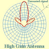
When selecting an alternative aerial do not automatically assume that an aerial with a higher gain will produce better results. Check the manufacturer's specification first.
 ..
..
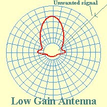
As can be seen from the illustration above, the polar diagram of a high gain aerial will consist of side lobes one of which may provide gain in the direction of the unwanted interfering signal. Changing the aerial type to one with lower gain and reduced side lobes will reduce the interfering signal.
| [Return to Aerial Checks] | [Top] |
Receiver Checks
Remove the aerial plug and fit an attenuator to the TV aerial socket.(The attenuator is to terminate the receiver input with a 70 ohm load - use the highest dB attenuation possible)
- If the interference has gone fit a High pass filter or braid breaker
- If the interference is still present, remove the lead from the
Tuner to the IF strip.
- If the interference has gone, there is direct pick-up on the tuner IF leads.
- If the interference is still present, wind the mains lead onto a
toroidal ferrite.
- if the interference has gone, it is mains-borne. Check that the RF by-pass capacitor on the mains input is fitted and has not gone open circuit. If the capacitor is satisfactory and the toroid cures the problem, re-wind the toroid so that it lies inside the receiver between the chassis and the cable strain-relief cleat. If only a partial cure is effected, it will be necessary to fit a choke/capacitor input filter.
- if the interference is still present, treat as for direct pick-up on the IF leads.
Receiver Faults
Direct pick-up in the tuner is usually due either to poor screening of the tuner section or inadequate RF de-coupling of power supply and control leads connected to the tuner.
Ideally, the tuner should be housed in a metal case to provide adequate screening. If any of the various leads to the tuner is suspected it may be necessary either to replace it with a screened lead or to fit a feed-through which incorporates an L-C filter which is more effective than a simple capacitor feed-through.
If the interference affects the sound only but is not affected by adjustment of the volume control, the pick-up is ocurring in the audio stages.
In audio stages using discrete transistors, this is due to rectification at the base/emitter junctions of transistors after the volume control. Fit 1nF capacitors and/or ferrite beads.
|
Fitting Ferrite beads and RF Bypass capacitors |
Capacitors should be disc ceramic and fitted with the shortest possible leads to keep inductance low. The ferrite bead should preferably be fitted on the base lead of the transistor but, where this is not possible, it should be fitted in the PC copper as shown. |
|---|
[Top]
Except in areas where the interfering signal is very strong, the interference will probably be entering the receiver from the aerial. Fitting a braid breaker or a High Pass Filter or a combination of the two will generally effect a cure.
Commercial filters are available, such as from Maplin Electronics and your local hi-fi dealer may also be able to supply them.
Alternatively, you could have a go at making your own.
|
Top: Toroidal Choke (Braid-Breaker) Bottom: Braid Breaker & High-Pass Filter |
|---|
The Braid Breaker.
The braid breaker is a toroidal choke for the HF bands and is made by winding several turns of co-axial cable through a ferrite ring, as shown. It is effective because interfering currents flowing down the braid create an external magnetic field and the device acts like a ferrite cored choke in the path of these currents. For wanted signal frequencies, however,equal and opposite currents are flowing in the inner and outer of the co-ax and their fileds cancel; the ferrite ring, therefore, does not impede signal flow.
The choke should be made using standard diameter co-ax and the ring should not be wound more than two-thirds full. The assembly can then be readily interposed between the co-axial downlead and the TV aerial socket.
The Combined Braid Breaker and High-Pass Filter.
This device prevents HF signal currents from flowing down the inner or outer of the co-axial cable. L1 has a low reactance to HF or VHF signals, thereby bypassing the interfering current, whereas C1 and C2 have high reactance to HF and VHF, effectively locking signals to the receiver. L2 provides a further short-circuit (to HF and VHF signals) across the connections on the receiver side of the filter.
At UHF the conditions are reversed. C1 and C2 presenting a low impedance path to signals to the receiver and the impedance of L1 and L2 is so high as to be ignored. R1 is for static discharge protection of the outer braid.
L1 and L2 are 4 turns of 20 SWG. 6mm inside diameter. 6mm long.
C1 and C2 are 4p7 disc ceramic capacitors.
R1 is 1M5 0.5 watt carbon resistor.
The PCB is single sided, 25mm by 50mm with grooves approx 1.5mm wide to
leave four areas of copper as shown.
The filter should be housed in a suitable aluminium case with one side
connected to the aerial downlead and the other side connected to the TV
aerial socket.