8-Input Video Switch
 Elsewhere on the website, you'll find construction details for a video switchbox
driven from the computer's Parallel Port. It was quite a few years ago and it was built in a hurry to meet a specific need.
Elsewhere on the website, you'll find construction details for a video switchbox
driven from the computer's Parallel Port. It was quite a few years ago and it was built in a hurry to meet a specific need.
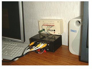
The switchbox itself used miniature relays to switch the video and, as it was to be mounted in the garage, appearance wasn't too important. To save time, at the computer end, I used a Parallel Port 'breakout box' which I'd made for experimental use many years previously.
When I moved home in 2007, I continued to use the same setup even though both switchbox and breakout box were now located indoors in
the 'hobby room'. Like many "temporary" jobs, it had tended to become more permanent and it was time to replace the unsightly
setup with something more suitable.
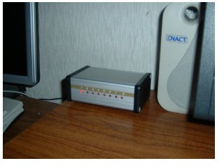 Instead of switching just four inputs, the new unit can switch 8 AV (composite) cameras and uses readily available transistors
to do the switching in place of the potentially unreliable electro-mechanical relays. As a bonus, it is, of course, totally silent
in use.
Instead of switching just four inputs, the new unit can switch 8 AV (composite) cameras and uses readily available transistors
to do the switching in place of the potentially unreliable electro-mechanical relays. As a bonus, it is, of course, totally silent
in use.
It still operates from the computer's Parallel Port because that's what the switching software uses but it is now completely
self-contained without the messy breakout box.
The Circuit
 |
 |
Parts List
- 8 x 4k7 0.25W resistors.
- 8 x 5k6 0.25W resistors.
- 8 x BC547B transistors.
- 8 x 3mm Red LEDs.
- 9 x panel-mounted phono sockets.
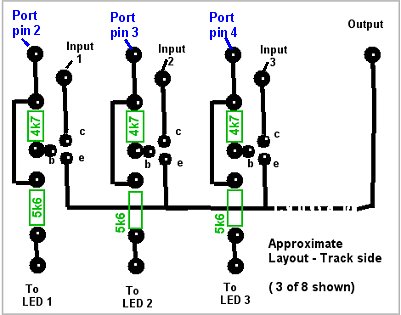
- plain copper-clad printed circuit board.
- etch resist transfers.
- etching solution.
- hookup wire.
- suitable case.
- old parallel port/Centronics printer cable.
For small quantities of resistors, Bitsbox.co.uk seem good value although I haven't used them personally.
I got the phono sockets and pcb from Maplin.
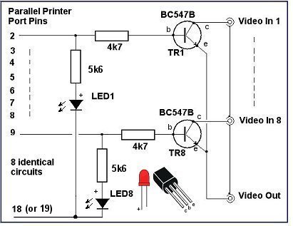
The circuit consists of 8 identical transistor switches operating as emitter followers. Each composite video input is connected to an NPN transistor's collector, all the emitters being connected together to provide a common video output.
When +5v is applied to a transistor's base from the parallel port (via a 4k7 resistor), the transistor switches on allowing the video to pass from collector to emitter. Almost any small signal NPN switching transistor should be suitable. The BC107B, for example is virtually identical to the BC547B except for its case style and lower maximum operating frequency.
An indicator LED is also connected to each parallel port output through a 5k6 0.25W resistor. In order to keep the load on the port's outputs as low as possible, try to keep the LEDs' series resistors as high a value as possible. The LEDs don't need to to be excessively bright. For the same reason, don't be tempted to buy LEDs with built-in resistors. They're designed to operate the LED at its maximum brightness and current, which we don't need.