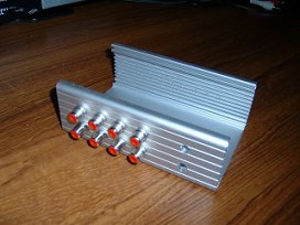
 Drill holes for the 9 phono sockets and the 8 x 3mm LEDs. And one for the parallel port cable. |
 Cut a piece of plain copper-clad pcb and lay out the circuit with etch-resist transfers. |
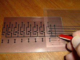
 This photo shows the board about half way through the etching process. |
 Once etched, remove from the solution and wash thoroughly. Note the use of PVC tape to mask off large areas to avoid unnecessarily depleating the etching solution. The tape tab at the bottom right is useful to grab the board in the etching solution. |
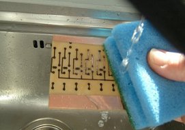 Clean away the etch resist with warm running water and a kitchen scouring pad. |
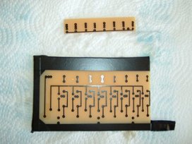
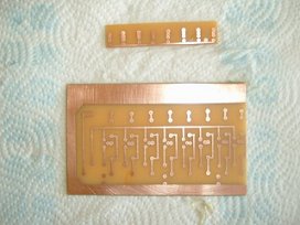 This photo shows the completed board ready for drilling. The small board at the top is to hold the 8 LEDs together instead of trying to get them to 'stick' in the holes independently! |
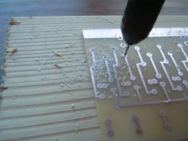 Using a 0.5mm drill-bit, use a small modelling drill to drill all the component holes. |
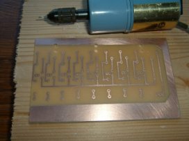 This photo shows the completed board with all the holes drilled. |
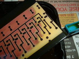
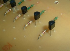 This photo shows a close up of the board showing 4 or 5 of the identical circuits. |
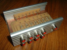 The completed pcb is fitted into the case. It's mounted with the copper side up to make it much simpler to attach the interconnecting wires. |
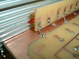 A close up showing how the common (0v) side of the LEDs is attached to the large area of ground copper on the main board.Ground pin 18 or 19 from the parallel port is soldered to this ground. |
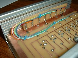 The +ve side of each LED is wired to its corresponding 5k6 resistor on the main board. |