Programming the ATmega328
The ByVac BV104
The ByVac BV104 is used to transfer the program from an editing environment on the PC to the ATmega328 chip. It's a USB to Serial interface and, the first time a USB cable is inserted, the computer will probably complain that its driver is missing.Windows 7 is smart enough to download and install the driver automatically. Otherwise, you'll need to download the driver from Silicon Labs. Once installed, the interface configures itself as a "Virtual COM Port" (VCP).
The Arduino IDE
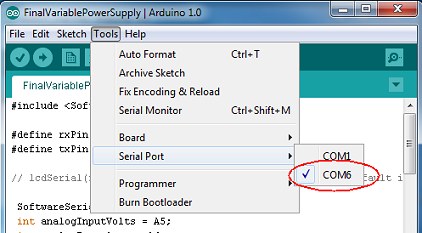
If you're already familiar with the Arduino, you'll probably already have its programming/editing software. If not, you'll need to download and install the Arduino IDE from the main Arduino website. With our Power Supply powered on and the USB lead connected, the Virtual COM Port should be visible to the Arduino IDE under its Tools | Serial Port menu.
Copy the following program and paste it into the Arduino IDE.
#include <SoftwareSerial.h>

#define rxPin 0
#define txPin 8

 SoftwareSerial lcd(rxPin, txPin);
 int analogInputVolts = A5;
 int analogInputAmps = A4;
 float vout = 0.0;
 float vin = 0.0;
 float amps = 0.0;

 float R1 = 9970.0;        // resistance of R1
 float R2 = 3330.0;        // resistance of R2
 float V5 = 5.00;          // Arduino supply

 int readVoltsADC = 0;
 int readAmpsADC = 0;

void setup(){
   pinMode(analogInputVolts, INPUT);
   pinMode(analogInputAmps, INPUT);
   delay(1000);

   lcd.begin(9600);                     // 9600, 14,400, 19,200 or 38,400 available on the ByVac LCD.
                                         // Arduino recommend no higher than 9600.
   lcd.print("\r");                      // Send 'CR' for the LCD to establish the speed.
   delay(500);

   lcd.print("ac1\r");                   // Clear display. Terminate data with 'CR' (0x0d)
   lcd.print("acc\r");                   // Cursor Off
   delay(500);
   lcd.print("adVolts\r");
   lcd.print("acc0\r");
   lcd.print("adAmps\r");
}

float fmap(float x, float in_min, float in_max, float out_min, float out_max) {
  return (x - in_min) * (out_max - out_min) / (in_max - in_min) + out_min;
}

void loop() {
   readVoltsADC = analogRead(analogInputVolts);
   readVoltsADC = readVoltsADC + analogRead(analogInputVolts);
   readVoltsADC = readVoltsADC / 2;
   vout = (readVoltsADC * V5) / 1023.0;
   vin = vout / (R2/(R1+R2));
   delay(100);


   readAmpsADC = analogRead(analogInputAmps);
   readAmpsADC = readAmpsADC + analogRead(analogInputAmps);
   readAmpsADC = readAmpsADC + analogRead(analogInputAmps);
   readAmpsADC = readAmpsADC / 3 ;      // get average of 3 readings

   amps = fabs(fmap(readAmpsADC, 512.0, 701.0, 0.0, 5.0));

   if (amps < 0) amps = 0.0;

   lcd.print("ac85\r");
   delay(100);
   lcd.print("ad  ");
   if (vin < 10) lcd.print(" ");
   lcd.print(vin);
   lcd.print("  \r");

   lcd.print("acc5\r");
   delay(100);
   lcd.print("ad   ");

   lcd.print(amps);
   lcd.print("  \r");

   delay(400);
}
The following lines, near the top of the program, allow you to calibrate the voltage reading on the LCD.
 float R1 = 9970.0;        // resistance of R1
 float R2 = 3330.0;        // resistance of R2
 float V5 = 5.00;          // Arduino supply
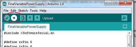
Hit the Upload button on the Arduino IDE and the program should be transferred to the ATmega328 in our Power Supply. If you connected the DTR signal from the BV104, the transfer will be automatic. If you didn't solder the connection, you'll need to hit the "Reset" button on the Power Supply's PCB to initiate the transfer.
Using an external meter, measure the actual voltage at the Variable Output terminals over the voltage range and compare the readings with the LCD. Tweaking the values of R1 and R2 in the program (and uploading the program to the ATmega328 again) should enable you to get the display accurate over the full range.
The following line of code in the program allows you to tweak the current display:
amps = fabs(fmap(readAmpsADC, 512.0, 701.0, 0.0, 5.0));The 512.0 and 701.0 are the digital representations of 0 amps and 5 amps respectively. The values shown should be accurate enough. Note that, although the digital values read from the ATmega328 are integers between 0 and 1023, they are shown as floating point numbers in the line above to coerce the Arduino IDE to treat them as floating point numbers for the maths. The values are derived as follows:
Output from the ACS712 = 2.5 + (0.185 volts per amp)

At 0 Amps, output = 2.5 volts

                                  1023
Analog To Digital Conversion =  --------
                                (5 / 2.5)

                             =  512   (integer value)


At 5 Amps, output from the ACS712 = (0.185 x 5) + 2.5

                                  = 3.425 volts

                                     1023
Analog To Digital Conversion      =  ----   ADC units per volt
                                      5

                                  = 204.6   ADC untis per volt

At 3.425 volts (ie 5 amps)        = 204.6 x 3.425

                                  = 700.755

As ADC units are integers,        = 701.0    (The '.0' is to ensure the Arduino IDE works in floating point maths)
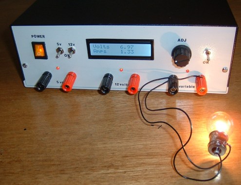
This photo shows a car bulb being used as a load to calibrate the power supply (at least up to 2 amps).