This project improves on my previous video switcher projects: A 4-input video switch and An 8-input transistor video switcher.
The previous circuits were designed to be controlled solely from a computer's parallel port where data on the port's output lines are used to select the desired video input source. For completeness, this new version can also be controlled from the parallel port but, additionally, the cameras can be selected manually from a panel-mounted switch or sequenced through automatically with a time delay variable between about 10 and 60 seconds.
This time, I've used a dedicated high quality video multiplexer IC to accomplish the video switching.
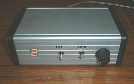
The project's circuit is split into two modules. One contains the analogue video switching circuitry and a 7-segment LED driver & display which indicates the selected video source. This module contains a 5 volt DC regulated power supply which requires a stable 9 - 12 volt DC input, This module can be used as a self-contained, stand-alone unit controlled from the computer's parallel port or a simple 'BCD' switch or other external switching arrangement.
In this project, I've routed the data lines (which control the camera-selection) to a rear-mounted socket instead of restricting the unit's flexibility with a hard-wired cable to a parallel port D-type connector. Additionally, the unit can now also be switched via a USB connection to the PC as parallel ports are getting quite rare.
The second module, which contains the automated switching and timing logic, can be built at a later date and simply plugged in without making any alterations to the first, video switching, module except for swapping over a couple of 5-pin header plugs. This second module obtains its 5v DC supply from the first one.
Module 1: The Video Switching Circuit
 The heart of the video switching circuit is the
MAX4312 integrated circuit from Maxim.
The heart of the video switching circuit is the
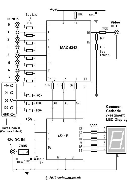
MAX4312 integrated circuit from Maxim.Up to 8 composite video sources can be connected to the chip's video input pins (pin 5 to pin 12). The Maxim data sheet shows each input terminated with a 75 ohm resistor but, in practice, I found these weren't necessary - in fact they stopped the video source working properly. I may have mis-understood the data sheet but I designed the printed circuit to allow for the resistors anyway, so they can always be added should a particular video source need one.
The selected video source is output on the MAX4312 pin 16. Resistors RF and RG control the gain of an internal video amplifier. Maxim suggest the following resistor values (in ohms):
| GAIN (dB) | RF (ohms) | RG (ohms) |
| 0 | 0 | o/c |
| 6 | 500 | 500 |
| 14 | 500 | 120 |
| 20 | 50 | 56 |
In practice, I found that a value of 470 ohms for RF and open-circuit for RG worked best with my setup. Again, I designed the printed circuit board to accept both resistors should they be required.
The video sources are selected by applying a binary (BCD) input to the Maxim chip's pins 3, 2 and 1. The least significant bit (D0) goes to pin 3, D1 goes to pin 2 and D3 goes to pin 1. As a stand-alone circuit, the computer's parallel port simply connects to these "address lines". Alternatively, a USB interface, such as the Velleman USB Interface could be used instead. An even simpler solution would be to control the lines with a BCD Switch of some sort.
Note that Maxim specify a 10K series resistor in each digital input line.
Also connected to the three "address lines" is a CMOS 4511B integrated circuit. This is a BCD to 7-segment decoder/driver and is used to drive a 7-segment LED display mounted on the front panel of our project.
Note the three x 100K resistors shown (optionally) between the three address lines and ground. In common with all CMOS ICs, all input lines must always "go somewhere." If the address lines are to be controlled by switches, these resistors should be fitted to make sure the inputs to the 4511B (and the MAX4312) are pulled 'low' when the switches are open. The switches (if used) would connect the inputs to +5 volts when they're closed.
The circuit is fed with a regulated 12 volt DC supply and regulated down to 5 volts DC with the 7805 regulator. I used 12 volts as the main supply simply because I use a 12v 5A regulated supply to feed all the cameras. Any 1A "wall adapter" would easily supply this circuit but it should be at least 9 volts DC, otherwise the 7805 regulator may not work very efficiently. Likewise, 12 volts is the highest I'd recommend, otherwise the 7805 might start to run too hot.
Even if you intend to build the automated switching and timing board, I recommend that you build and test this circuit first and sort out the hardware....