ATmega328 Camera Controller
Introduction
This article was inspired by my recent re-kindling of interest in photography. Times have moved on a bit since I last used an SLR ( a Minolta SRT-101), the cost of modern DSLRs being a limiting factor until recently.However, the specifications of "entry level" DSLRs now are what would have been considered to be for "professional level" cameras only a few years ago so I recently took the plunge and treated myself to an early Christmas present - a Nikon D3100.
Naturally, my renewed interest in photography wouldn't detract from my interest in electronics or programming and the following project nicely combines all three.
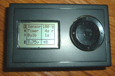
The gizmo I have in mind will be dual-purpose: Primarily it will be a camera controller to fire the shutter automatically when an external stimulus occurs - a lightning flash or a popping balloon, for example, or at regular intervals controlled by an internal timer.
But virtually the same hardware would allow the unit to function as a 'simple' slave flash controller - the slave flash being fired with the same external stimulus that fires the camera shutter (after an adjustable time) or when the camera's own flash is detected (taking into account any pre-flashes).
Firing the shutter remotely
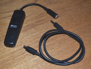
I suspect it would be virtually impossible to get hold of a plug to fit the Nikon's remote shutter socket and, as the D3100 doesn't have IR capability, the simplest (only?) solution was to buy an inexpensive Remote Shutter Release Cord from ebay and cut off the button unit to leave a three-core cable with the plug attached - after having opened the button unit to determine which wire is which.The wires in the remote release that I bought are as follows:
Other remotes may be wired differently but as they're basically just two normally open switch contacts, it won't harm the camera if they're wired incorrectly while testing - although the shutter may act oddly.
 |  |
|
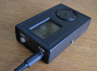
In the finished project, the cable with the Nikon plug on one end has a 3.5mm stereo plug fitted on the other end which plugs into a matching socket on the project. In order not to waste the button unit that I'd cut off, I fitted it with an in-line 3.5mm stereo socket. |
When I'm not using the project, I can "re-attach" the button unit to the cable and use the remote release normally. Meanwhile, the cable with the Nikon plug just has flying leads attached while I develop the best triggering method. |
 The are several methods to connect the camera's focus & shutter contacts to the ATmega328
processor. They range from simple switches using transistors or MOSFETS to what I consider to be a "safer" method using
opto-isolators which have the advantage of keeping voltages from the DIY electronics completely separate from the expensive camera's electronics.
The are several methods to connect the camera's focus & shutter contacts to the ATmega328
processor. They range from simple switches using transistors or MOSFETS to what I consider to be a "safer" method using
opto-isolators which have the advantage of keeping voltages from the DIY electronics completely separate from the expensive camera's electronics.
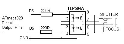
I've used a TLP504A opto-isolator. It has two channels in an 8-pin DIP package so is ideal for controlling both focus and shutter.
I've connected the outputs from the opto-isolator to a standard 3.5mm stereo socket such that the camera's focus connection is to the stereo plug's 'ring' contact, the shutter connection is to the plug's tip and the common is the the plug's 'sleeve' connection. Note that none of the socket's contacts are connected to the project Ground. The Controller's software has an adjustable time delay between activation of the focus and shutter opto-isolators.
The setup works fine with my Nikon D3100 but other cameras will require different
pinout arrangements.
The Photo Sensor - Part 1
Having sorted out how to fire the shutter, the next thing to consider is when to fire the shutter. In order to keep the project small and portable, I decided to have only a simple photodiode light sensor on board.
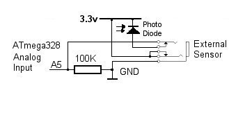 The photodiode is connected to an analog input pin on the ATmega328. By changing the
processor's analog voltage reference to INTERNAL, the diode is fairly sensitive to changes in light level.
The photodiode is connected to an analog input pin on the ATmega328. By changing the
processor's analog voltage reference to INTERNAL, the diode is fairly sensitive to changes in light level.
The photodiode is connected to the ATmega328 via a normally closed contact on the 'tip' connection of a second 3.5mm stereo socket. Inserting a plug will disconnect the photodiode and route the ATmega328 input to the outside world. Here, it could be connected to a more sensitive light sensor or a microphone, for example.
The 'ring' connection on the 3.5mm socket provides 3.3 volts to the outside to
be available to supply an external photodiode or for powering a small amplifier or an electret microphone. The mono MIC input on most PC sound cards
is wired this way so the socket should be compatible with a PC type microphone.
That's about all the hardware devoted to the camera trigger but the photodiode can also be used to trigger an auxiliary (slave) flashgun. The next section shows some research I did while developing the hardware for the the slave flash trigger.